Microstructure Generation and Meshing — Lesson 3
Microstructure Generation
Microstructures can be measured experimentally via electron backscatter diffraction (EBSD) or can be synthetically generated via software like DREAM.3D. In either case, the microstructure is commonly stored in a voxelated format in terms of a .vtk file. We need the grain ID (unique number identifying which grain the current voxel belongs to) and the crystal orientation (in terms of Euler angles) for each voxel in the .vtk file. A synthetic microstructure .vtk file used in this course can be downloaded here:
Microstructure Meshing: Structured Hexahedral Mesh
Two meshing methods are introduced in this course. In the first method, we simply convert each voxel into a hexahedral (Solid 185) element. A preprocessing Python script can be downloaded here:
Download the Python script here.
The user can specify the input file format, in this case, we are reading an input .vtk file:

Additionally, a scaling factor can be applied to scale the dimensions in the input .vtk file as needed:
![]()
Here we use this factor to scale the input domain to a width of 1mm. Upon running the Python script, an external input file in the form of an Ansys .cdb file is generated. To proceed, we will import the .cdb file into the External Model for subsequent simulation. Open Ansys Workbench, and expand Component Systems in the Toolbox. Locate the External Model and drag it into Project Schematic:
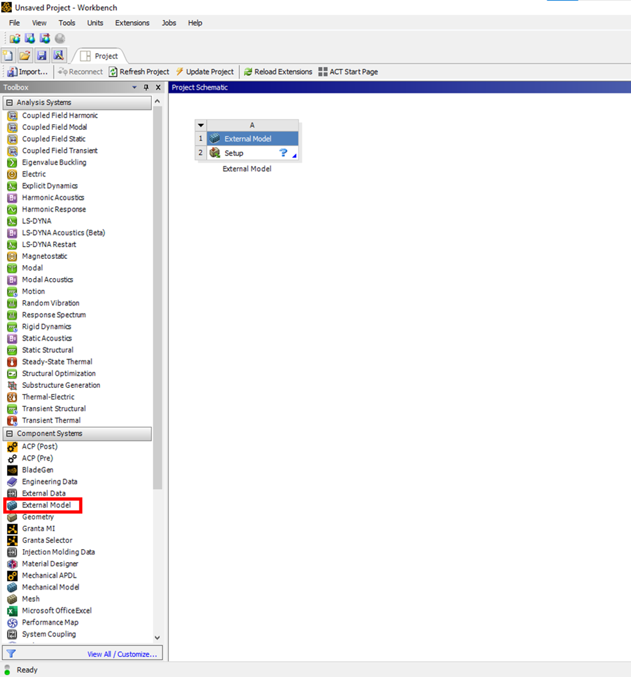
Right-click on Setup > Edit > Location > Browse, and locate the .cdb file generated by the Python script.
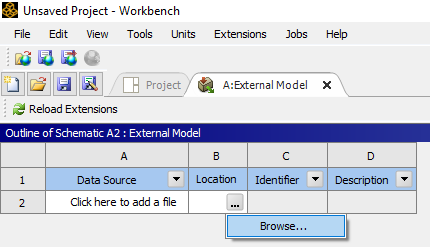
Once the file is selected, right-click on the file name just imported (2nd row under the Column Heading "Data Source" ). This will populate the Properties of File in the panel below. There, make sure that the Unit System selected is in mm, as shown below:

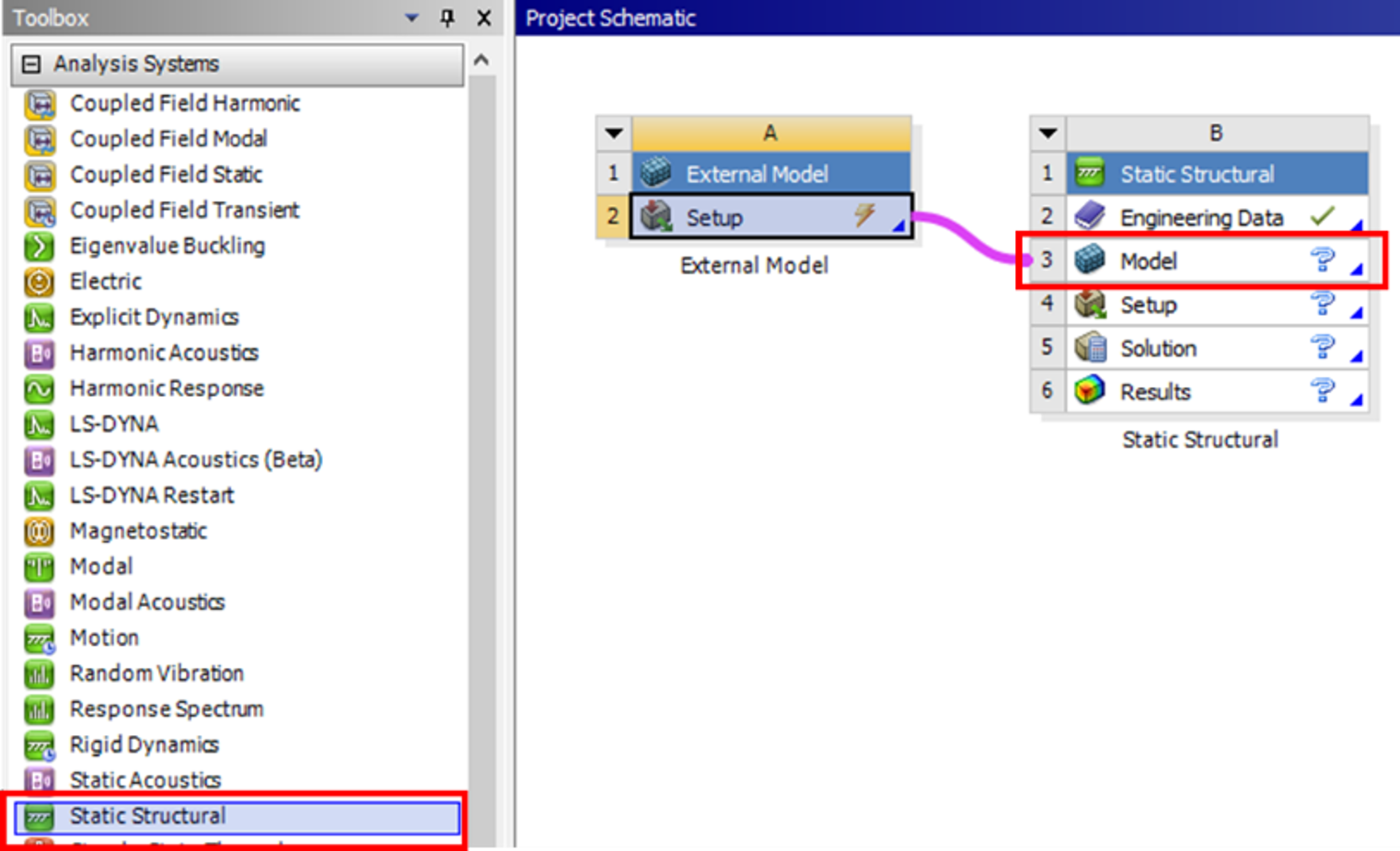
Click on the Project Tab to return to Project Schematic. From Analysis Systems, drag and drop a Static Structural block to the right of the External Model block. Connect the External Model block to the Model component of Static Structural.
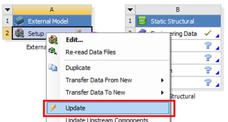
Update the External Model block by right click > Update:
This completes the mesh setup and transfer for the hexahedral meshing option. To view the mesh, double-click on the Model component to open Ansys Mechanical:
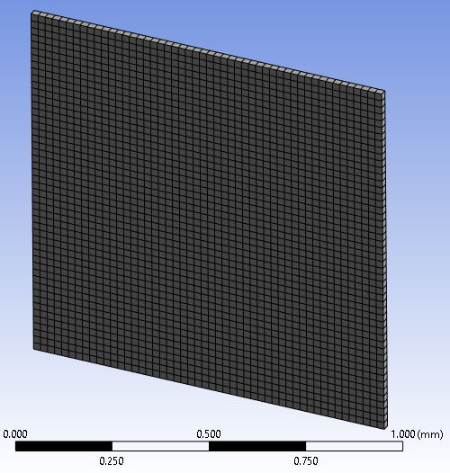
It is a structured mesh with 2500 linear hexahedral elements.
Microstructure Meshing: Unstructured Tetrahedral Mesh
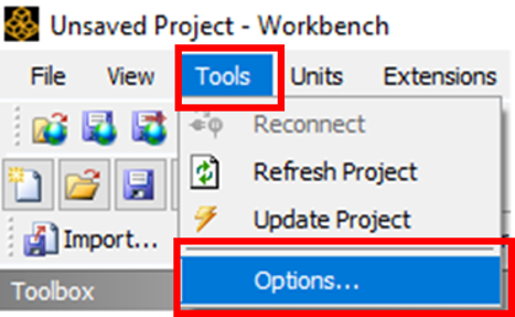
When directly converting voxels into hexahedral elements, the grain boundaries inside the microstructure are stair-stepped and can lead to artificial local stress concentration. To minimize the effect of stair-step grain boundaries, the second meshing method smooths the grain boundaries and meshes the grains with tetrahedral elements. Note that this feature is only available with Ansys version 2023R2 (or newer). Open Ansys Workbench, and right-click on Tools > Options.
In the new panel, under the Appearance tab, enable Beta Options:
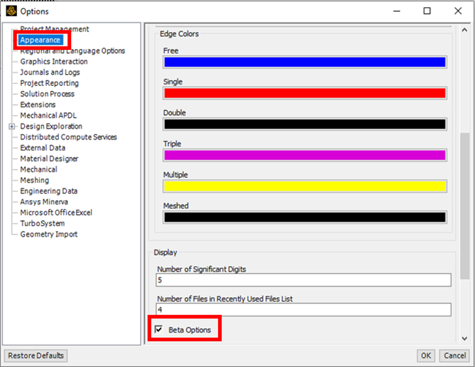
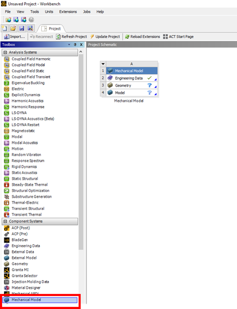
Note that you only need to change this once. Expand Component Systems in the Toolbox. Locate the Mechanical Model and drag it into Project Schematic:
In the Geometry component, right-click> New SpaceClaim Geometry (You can use DesignModeler or Discovery):
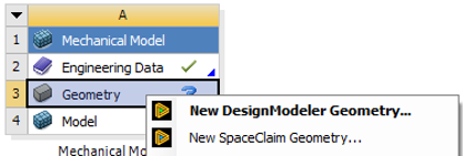
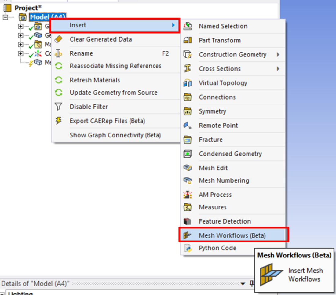
Open the CAD tool, and create a dummy geometry (can be any geometric entity like a cube or sphere, which will be suppressed later). Once the dummy geometry is created, close the CAD tool, and double-click on the Model component to open Mechanical. Right click on Model > Insert > Mesh Workflows (Beta):
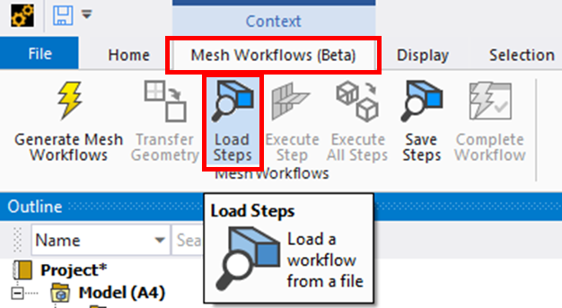
Change to the Mesh Workflows context bar, right-click Load Steps:
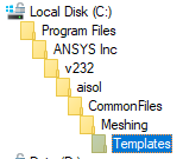
Navigate to the Ansys installation directory (in this example case, it is C:/Program Files/ANSYS Inc/v232). Starting from the installation directory, further, navigate to aisol/CommonFiles/Meshing/Templates.
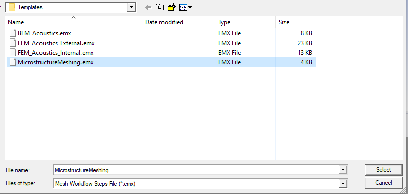
In the Templates folder, load the file MicrostructureMeshing.emx:
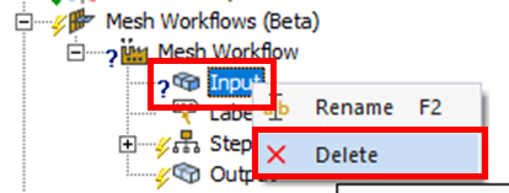
In the Project tree, expand the Mesh Workflows (Beta) object, right click on Input > Delete:
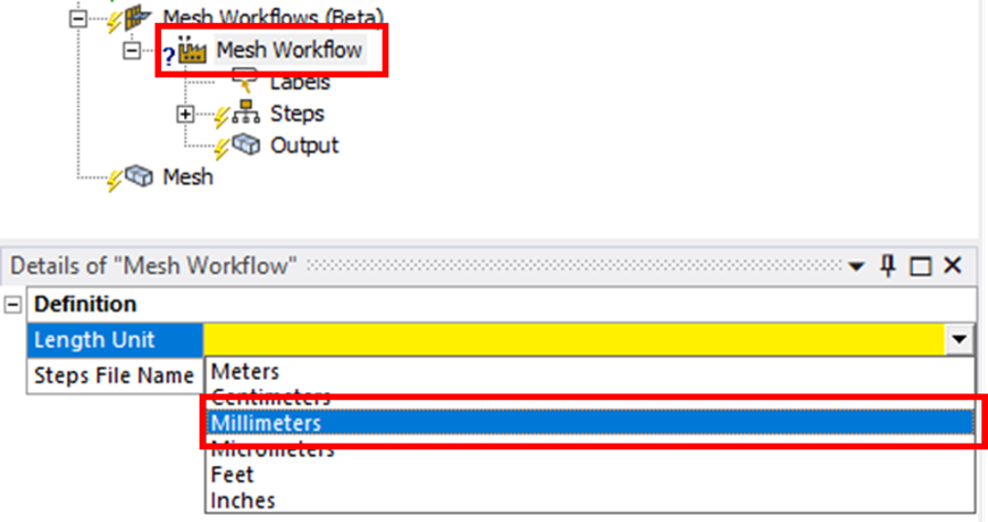
Right-click on Mesh Workflow, in the Details window, under Length Unit, and choose Millimeters:
Before you proceed, you need to download the Python conversion script that converts the geometry and grain information in the input .vtk file into an Ansys APDL model in .dat format.
Download the Python conversion script here.
Upon running the conversion, the file Synthetic.dat is generated, containing information on the grain ID.
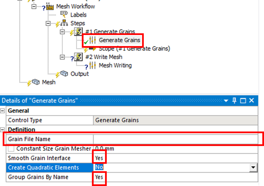
Return to Mechanical. Expand the Steps and all of its children. Right-click on Generate Grains, in the Details window, under Grain File Name, and click on the three dots to navigate to the Synthetic.dat we just generated. Make sure that Smooth Grain Interface and Group Grains by Name are set to Yes. Quadratic elements can be generated by setting Create Quadratic Elements to Yes, but is not selected in this course to save computational time.
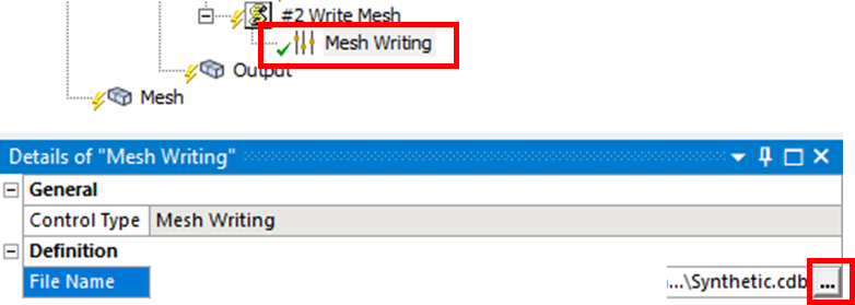
Rick click on Mesh Writing, in the Details window, under Grain File Name, click on the three dots to navigate to the desired output folder, then enter Synthetic.cdb (including “.cdb”) as the output file name.
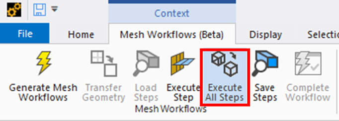
In the Mesh Workflows (Beta) context menu, right-click Execute All Steps:
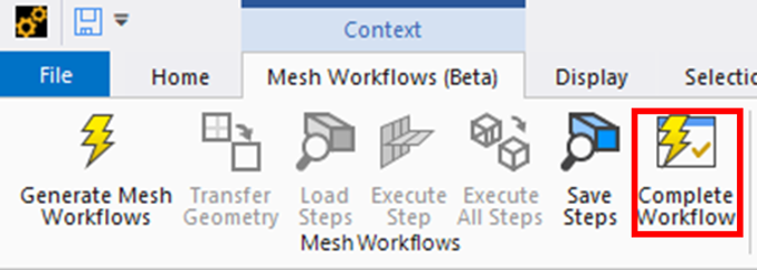
When all steps are completed, right-click Complete Workflow:
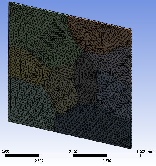
The output mesh file is written into the file Synthetic.cdb, and contains 15200 linear tetrahedral elements:
Exit Mechanical and return to the Project Schematic. Follow the steps outlined in the previous section to import the .cdb file as an External Model and connect to a Static Structural component. Remember to make sure the length unit is set to millimeters when importing the .cdb file into External Model.
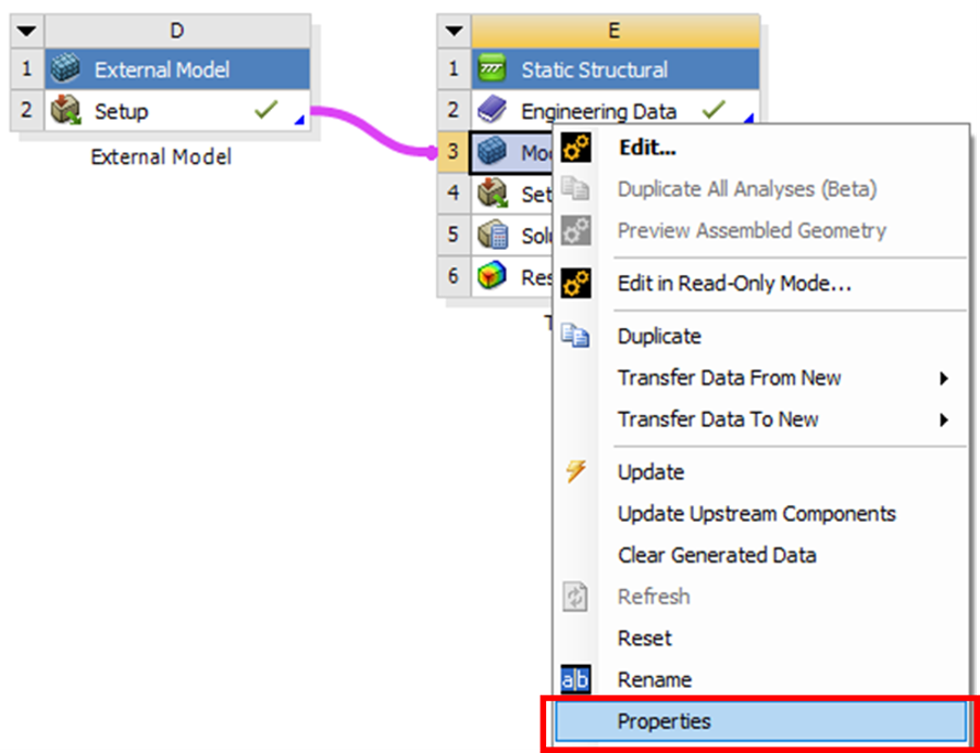
Right-click on the Model component of the Static Structural block, and select Properties:
Set Object Renaming to Off:


