-
-
September 18, 2025 at 9:53 am
vighnesh.nandavar
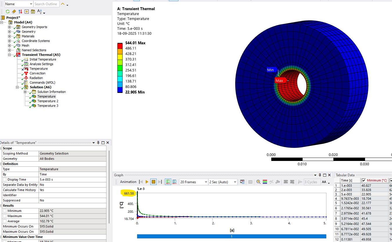
SubscriberI am simulating the cooling behaviour of a rocket motor. The below image depicts a small portion of the engine just to make my understanding clear.
What I intend to do : The engine burns for 15s. The inner surface becomes completely hot (I do not know how much, but I intend to find out by trial and error). It is then allowed to cool. I am trying to simulate this cooling behaviour.Compare the result from the actual data I have.
What I have done:
- From the image attached above, I have given an APDL command to have the initial temperature to 700C only on the inner surface of the disc since I dont want the entire disc to be heated + I have given the boundary conditions as needed.
- Refering to some other posts, I also tried simulating this analyis in 2 steps. Step 1 being steady state and step 2 achieving a cooling. But then I thought, I am sure that the entire system did not achieve a steady state in 15s. Due to this, the simulation result was quite obvious. The temperature on the outer surface decayed gradually. However, when I took the real values on the surface after 3 minutes, the temperature began rising. This suggested that the inner surface was really hot and now it is distributing the heat outwards.
- Referring to point 2, becomes the reason for me to give an initial temperature to the inner surface. I see that the results are in the trend as expected. The surface heats up over time
What I am confused and need some help:
The complete cooling of the disc shown above takes place within 2s. Which is not the case in reality. I tried making convection (which is dominant above radiation in this case) film coeff zero. The results remained the same. I am guessing the reason is because, giving an initial temperature is only for a fraction of a second. But how do I make this fraction of a second much longer? I would think about steady state in the begining but I am unaware of the temperature on the inner surface.
I would really appreciate some new perspectives and suggestions.
Best
Viggy -
September 19, 2025 at 8:21 am
Dennis Chen
SubscriberI can't see rest of the model or the size of everything to get a sense of time scale of conduction through the ring but the general logic is easy to explain
1) your inside is one side of your boundary - hot (700c)
2) at t=0, what is the temperature expected on the outisde of your ring? add a boundary there
3) with just 1 and 2, heat flux should be calculated based on conduction. Heat flux requires a delta T gradient which is what you need to define.
4) you can then add convection and radiation effects to see how it changes the results from #3, the structure should lose more heat obviously when compared to conduction only mode of heat transfer.
build it step by step and you should get it, you may be overthinking it and therefore missing simple conditions that you need to set.
-
- You must be logged in to reply to this topic.


- The legend values are not changing.
- LPBF Simulation of dissimilar materials in ANSYS mechanical (Thermal Transient)
- Convergence error in modal analysis
- How to model a bimodular material in Mechanical
- APDL, memory, solid
- Meaning of the error
- Simulate a fan on the end of shaft
- Nonlinear load cases combinations
- Real Life Example of a non-symmetric eigenvalue problem
- How can the results of Pressures and Motions for all elements be obtained?

-
3892
-
1414
-
1256
-
1118
-
1015

© 2025 Copyright ANSYS, Inc. All rights reserved.


