TAGGED: thermal-analysis
-
-
March 16, 2026 at 9:55 pm
patrick.miller4
SubscriberI have been struggling to understand some of the behavior I have seen when analyzing a geometrically simple interaction between a few surfaces. I have simplified the original problem and provided an excel spreadsheet summarizing the results in this post.
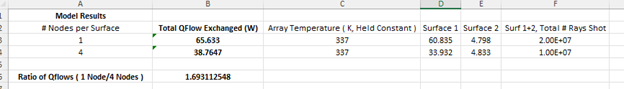
Initially, there was a pair of surfaces, each with one node which interacts with a solar array. When analyzed as a SS solution, the two surfaces and the solar array have a Qflow between sub models totaling 65.633.
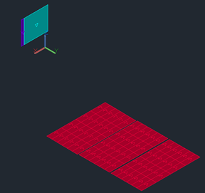
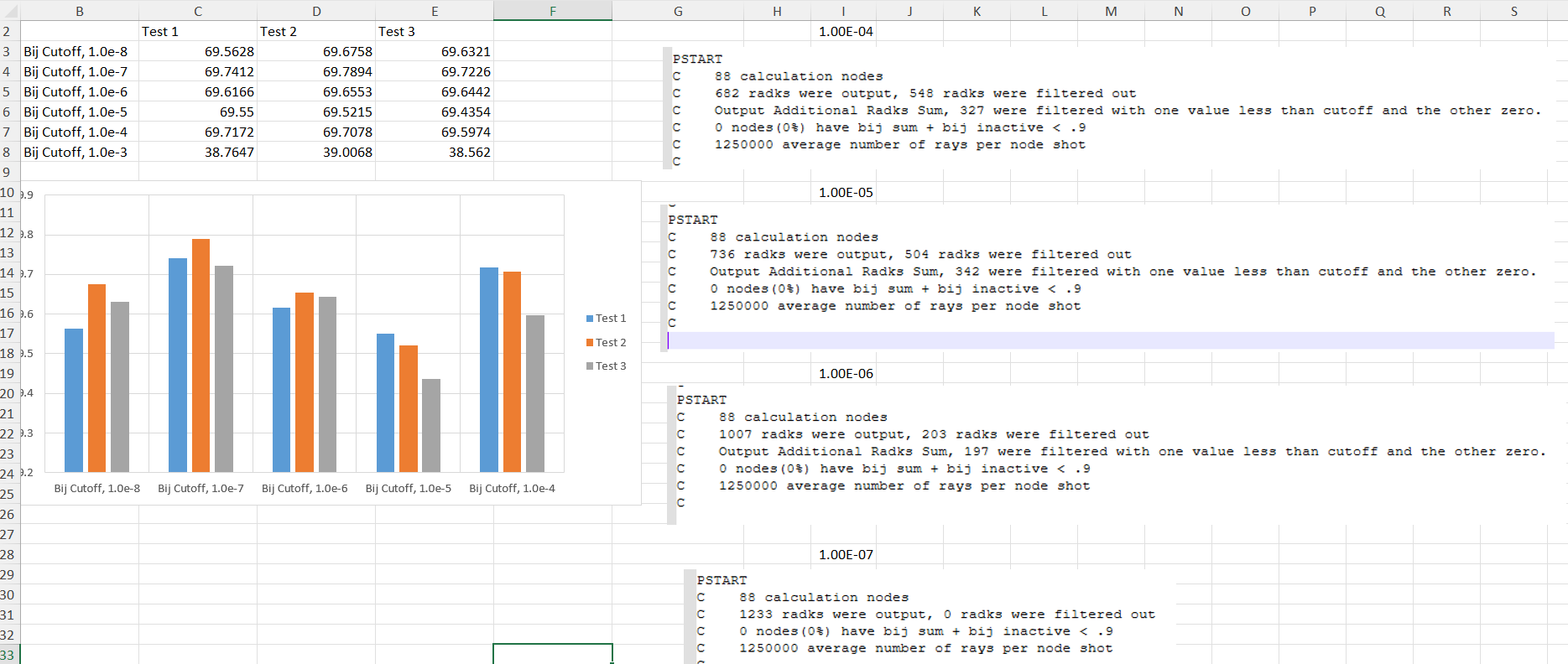
When adding nodes to the model, I noticed a significant decrease in the Qflow between sub models. With only a few additional nodes, the Qflow value drops to 38.76 W.
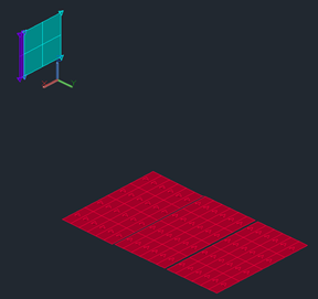
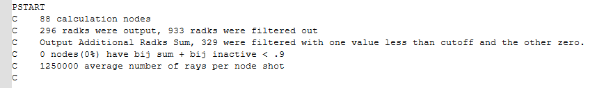
While this is common when looking at systems which are under nodalized to begin with, this does not seem to be the case here. There is no meaningful change to the view factors, and I have edited the two cases to shoot a similar total number of rays regardless of node count. I have tracked down a difference wihtin the .k file that explains why the model is reporting this difference. The Area*e*Bij value changes at the same rate as the report Qflow between sub models.
Given the simple nature of geometry, hand calculation should produce reasonably accurate results. When performing this calculation, it predicts a total radiative Qflow of ~69W. Slightly higher but in family with the 1 node results, but nearly 2x the multi node value. Given the two models have the same calculated view factor, same radiative environment, same material properties, and everything is modeled as 100% specular surfaces, I cannot think of a reason the Bij would so severely decrease between the two models.
My intuition and physical understanding trusts the hand-calc/one-node results. However, given the implementation of TD over many aerospace programs, I do not entirely distrust the model results. Let me know if you can think of a rationale behind this Bij decrease between the two nodalization schemes.
Â
Thank you.
-
March 19, 2026 at 6:51 pm
Doug Bell
Ansys EmployeeI am trying to figure out how you can share your model with me. In the mean time, can you provide the summary of the radiation calculations found at the end of the *.k file? Is should look something like this but may have additional or missing lines based on the model and calculation:
C Â Â 36 calculation nodes
C Â Â Â Â There were 15 number of positions
C Â Â 184 radks were output, 206 radks were filtered out
C Â Â 0 nodes(0%) have bij sum + bij inactive < .9
C Â Â 50000 average number of rays per node shotMy first guess is that the Bij cutoff factor (on the rak output tab of the radiation task) is too high resulting in a relatively large number of filtered radks. The Bij cutoff prevents overly full matrices with extremely low values. The more nodes that are in the model and the lower the emissivity of the surfaces, the lower the Bij cutoff should be. A good starting point is the inverse of 10x the number of calculation nodes. From there, you will want to decrease the value until the solution stops changing.
-
March 19, 2026 at 7:45 pm
patrick.miller4
SubscriberHello Doug, thanks for the response.
Ive attached a screenshot of the Radiation Tab "Radk Output" tab in case it would be helpful, alongside the requested screenshot of the .k file. It does seem as though a large ratio of radks were filitered in both cases, which seems like a good insight on your end. While the value of 0.001 I currently have is close to the recommended 0.0013 (1/740), Ill look into running some cases with smaller cutoffs and see if this produces a converging result.
These are for the single node surface.
Â
These are for the multi-node surface.
For reference: The case with 1 node surfaces is set to shoot 10M rays from the two surface nodes, while the multi-node case shoots 1.25M from all nodes. This is done to roughly equate the # of rays coming off of the purple/teal surfaces in the different cases. This is the reason for the difference in average rays shot for each case.
Â
Thanks again!
-
-
March 19, 2026 at 8:53 pm
Doug Bell
Ansys EmployeeSomething isn't right. You certainly have enough rays. It appears you are using either top/bottom specific calculations or you have double-sided surfaces since I see what I assume is 36 nodes on the red surfaces. I personally prefer to reduce the Bij Cutoff than add small radks back in, but they effectively do the same thing. I will continue search for ways that you can share your models with me since that will be the most efficient way to figure out what is happening.
-
March 20, 2026 at 2:11 pm
patrick.miller4
SubscriberÂ
Your initial feeling seemed to be correct! I ran a handful of cases with decreased Bij cutoff values and it quickly brought the multi node Qflow in line with the one node and hand calculation results. Ive attached a summary of what Ive done here for reference. These reuslts are all for the multi node surface, comparing the total Qflow between the purple/teal and red surfaces.
If this results still seems unexpected, Im happy to share the model for you to take a look yourself, just let let me know if you find a way to transfer it. Thank you for the help!
Â
-
-
March 31, 2026 at 8:44 pm
Doug Bell
Ansys EmployeeIt appears you are getting expected results. Note that the Bij is similar to the product of view factor and emissivity (not accounting for reflections). Therefore, if the view factor from one surface to the other is less than 0.1 and the emissivity of the surface is less than 0.01, then the Bij will be less than 0.001 (the default Bij cutoff).
Let me know if you found this helpful or have other questions or concerns.ÂKind regards,ÂDoug
-
- You must be logged in to reply to this topic.
-
5879
-
1906
-
1420
-
1306
-
1021
© 2026 Copyright ANSYS, Inc. All rights reserved.


