-
-
March 24, 2026 at 5:06 pm
peltjm26
SubscriberI am modeling a linticular-shaped pipe buried in sand. I created a fluid region and a "sand" region. The temperature of the sand starts at an initial temperature but will slowly go down over time as the fluid heats up. The fluid inlet is constant, but the fluid outlet and the temperature will go down as the surrounding sand cools down. I have made a mesh just fine and created all the needed named sections, but once I go to the Fluent setup nothing is there except the inlet and outlet arrows. I was wondering if anyone could help with this issue. I have attached a few pictures of the issue. Thank you.

-
March 25, 2026 at 12:50 am
Ahmed Hussien
Ansys Employee
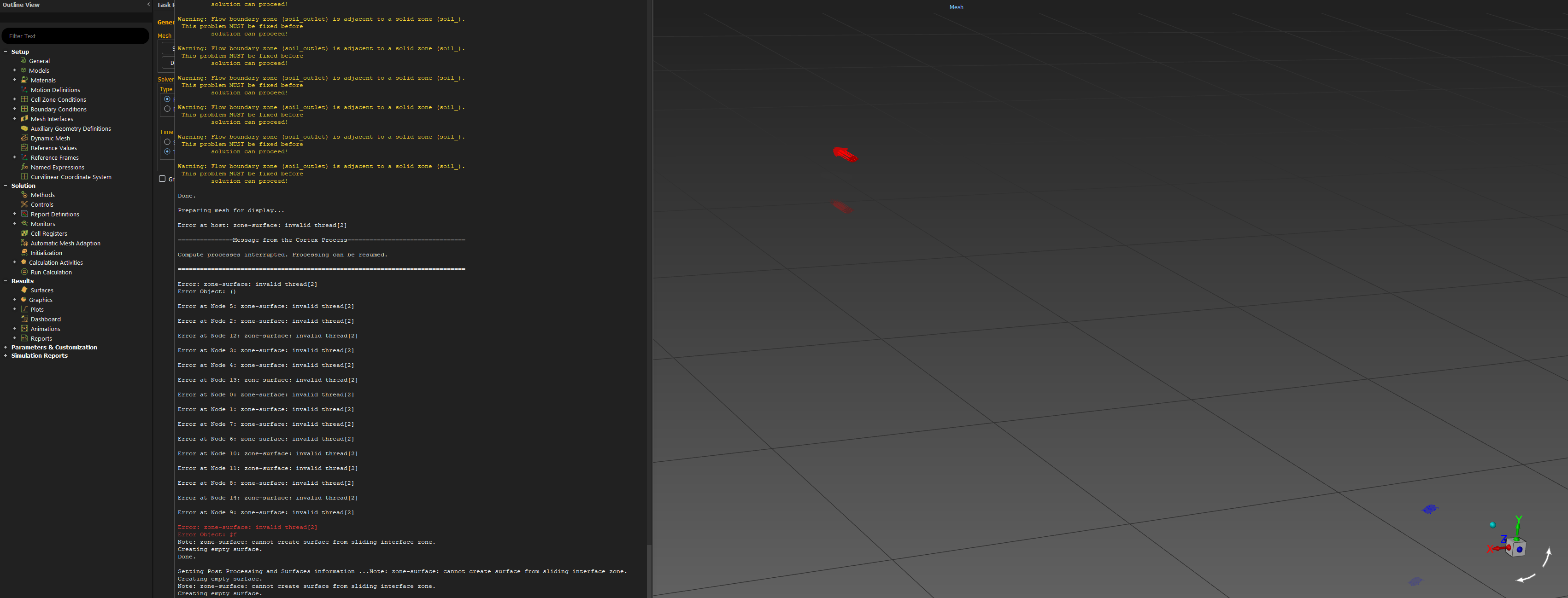
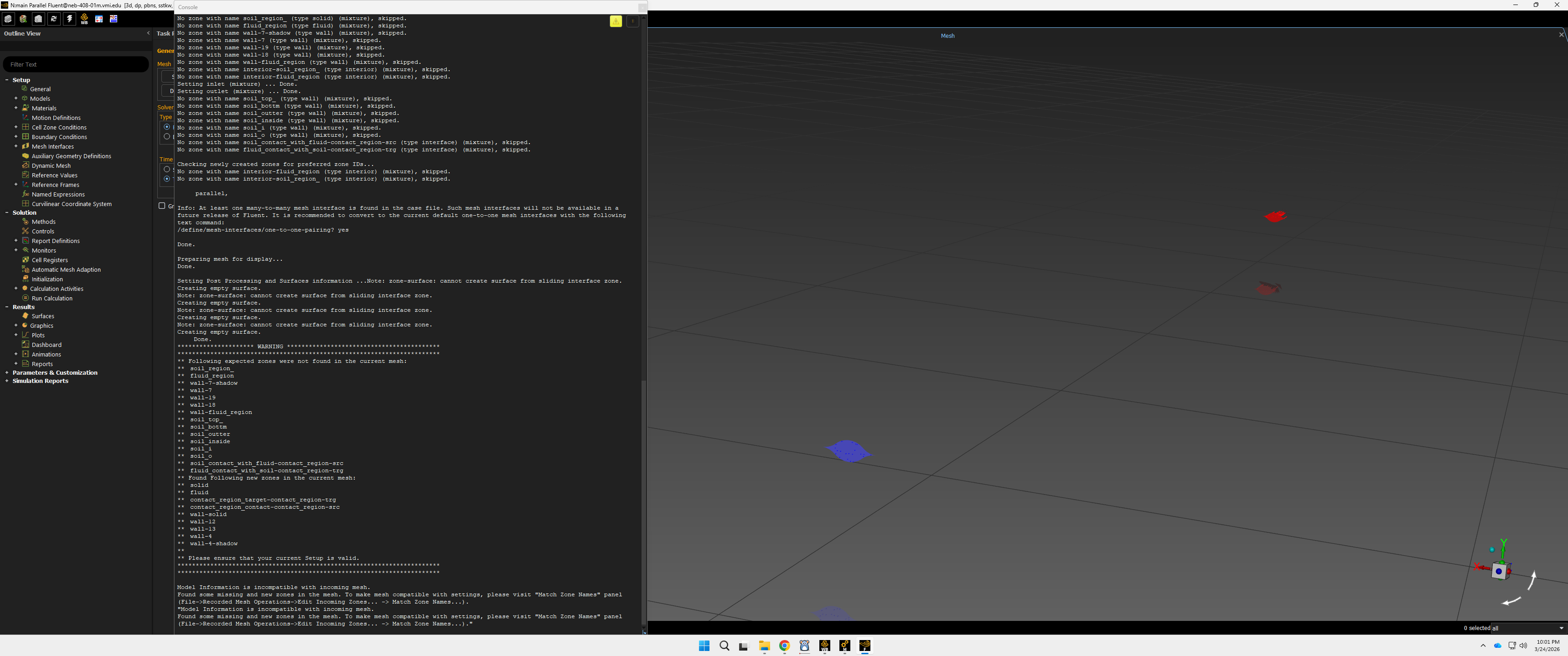
The issue you are encountering is most likely related to incorrect boundary condition assignment. There is a warning indicating that a flow outlet has been applied to a solid region, which is not physically correct. Outlet boundary conditions must always be applied to a fluid zone, not a solid zone. To resolve this issue, change the outlet boundary condition applied to the solid region to a wall, and ensure that the interface between the fluid and sand regions is also defined as a wall (for standard Conjugate Heat Transfer modeling, this should be a coupled wall). The correct setup depends on how you intend to model the sand. If the sand is modeled as a solid, which is the typical approach for CHT, it should be defined as a solid zone, with heat transfer occurring through conduction in the sand and convection in the fluid. The interface between the fluid and solid must be a coupled wall, and no inlet or outlet boundary conditions should be applied to the sand region. If instead the intention is to model sand movement or interaction with air, then a multiphase model must be enabled. In that case, the Eulerian model with a granular phase can be used to represent the sand. This allows the sand to behave as a fluid-like phase, where inlet and outlet boundary conditions can be defined, and the sand region can be initialized using an appropriate volume fraction.
-
March 25, 2026 at 2:04 am
-
March 25, 2026 at 7:37 am
NickFL
Subscriber- Where did you create the Mesh? In ANSYS Meshing or in Fluent Meshing or a 3rd Party?
- It seems like you are running a journal file, is this correct? Are all the boundary conditions applied with EXACTLY the same names? Seemingly small changes in names can lead to the script not working. That is why you are getting that long warning about faces not being in the mesh.
- Go to the Tasks Panel and click Display. This opens a window. You can turn on the faces with the new names here. Because they likely have different names now, the case file did not activate them for viewing. For example if your old model had a boundary condition Wall that was turned on, the new model with a boundary condition Walls would not be activiated.
Hopefully this points you in the right direction.
It looks like you are using Fluent in Workbench. When you updated the geometry there something called the “Match Zone Names” panel. You may be able to use that to get all your boundary condtions assigned correctly and then the will appear in the Graphics Window. I don’t use Workbench but try:
Found some missing and new zones in the mesh. To make mesh compatible with settings, please visit “Match Zone Names” panel
(File->Recorded Mesh Operations->Edit Incoming Zones… -> Match Zone Names…).”
-
- You must be logged in to reply to this topic.
-
5799
-
1906
-
1419
-
1305
-
1021
© 2026 Copyright ANSYS, Inc. All rights reserved.
