3D Design

3D Design

Topics related to Ansys Discovery and Ansys SpaceClaim.

SpaceClaim & Sweep/Pull

    • 1260960796
      Subscriber

      Assume there are many lines in SpaceClaim, how can I sweep all of them and apply a certain section pattern at once?
      I know "pull" function, but when the lines are discontinous, this function can't apply a certain section pattern at once. It's suggested that create the same patterns at all the endpoints of lines and "pull" them one by one, which is so complicated.


    • peteroznewman
      Subscriber

      The Pull tool has a Sweep button that allows you to select a face to sweep along a trajectory.  The face becomes the cross-section of the sweep.  A surface can be created that has 3 faces.  Here is a surface selected with the Pull Tool and the Sweep Button pushed then the arc selected for the Trajectory.

      Here is the result:

      Please provide an image of what you want to accomplish.

      • 1260960796
        Subscriber

        Actually, I think you misunderstand my attempt on the opposite. What I want is to sweep lots of different lines by a face, instead of sweep a line by creating several faces.
        For instance, as the figure below shows, there are splines of a simple truss. I want to sweep them by a section pattern(such as an "I-shaped" face). How can I sweep all of lines at once?

    • peteroznewman
      Subscriber

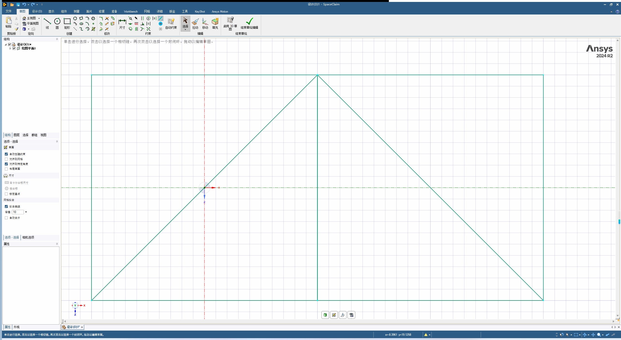
      With that image and some more description, I believe you wish to create beams with a cross-sectional profile such as an I-beam shape for structural analysis.

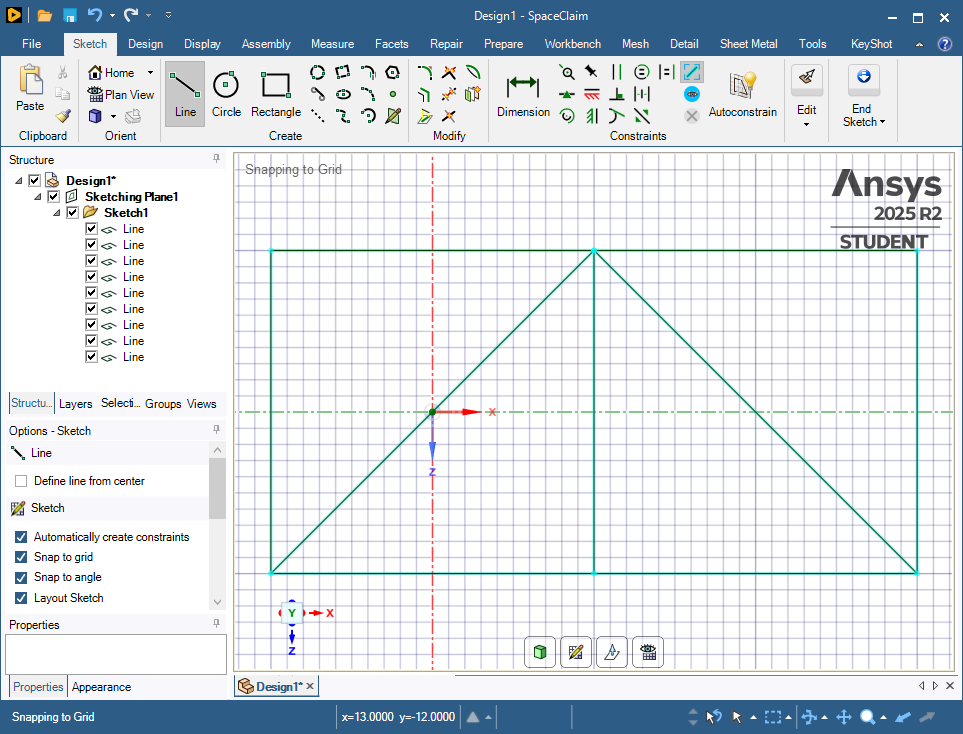
      Here is your truss created using a Layout sketch:

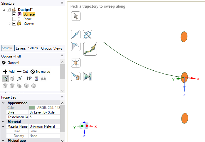
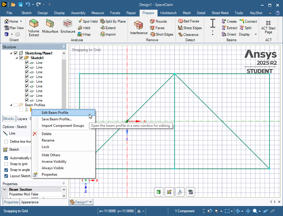
      Click on the Prepare Tab and pull down the Profiles button to select an I profile.

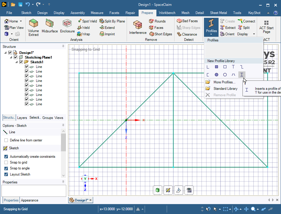
      In the Structure, there is an I profile that you can edit the dimensions.

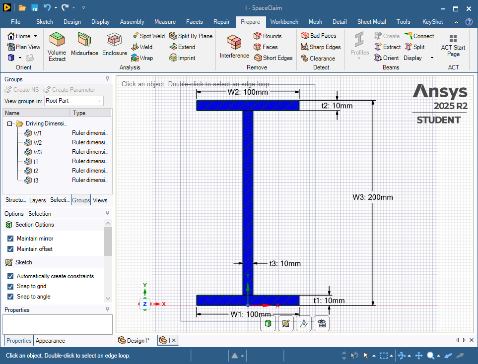
      Now all the dimensions are available to edit.

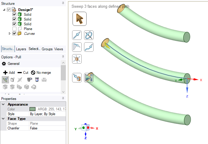
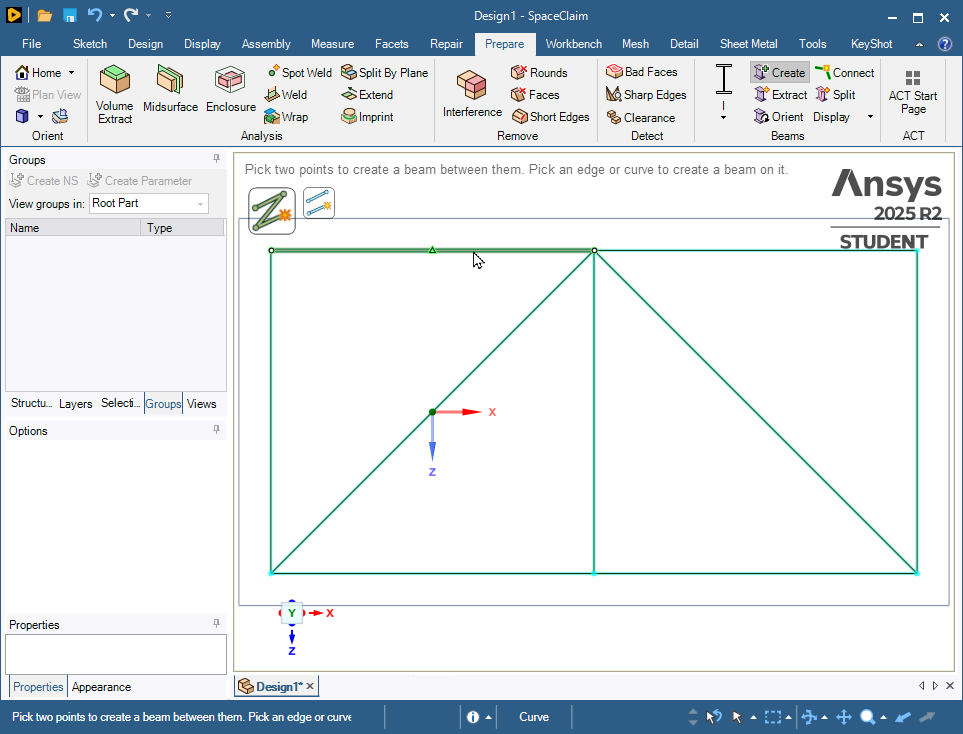
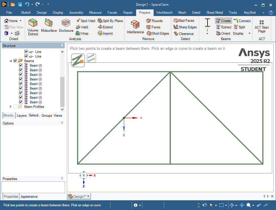
      You can close the I tab at the bottom of the graphics window to get back to your truss sketch. Now use the Create button to make beams from the lines. Every beam clicked gets the same profile.

      Click on the Workbench tab then the Share button then the green check to connect the beam ends to each other.

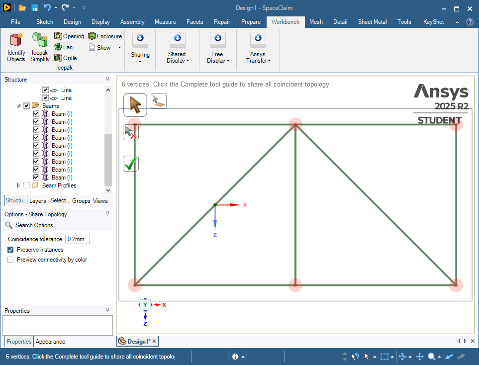
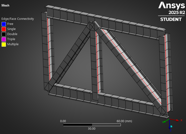
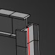
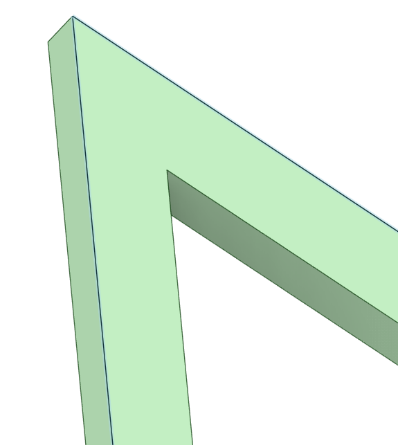
      When you open this file in Mechanical, you will have an I-beam structure that you can support and load.

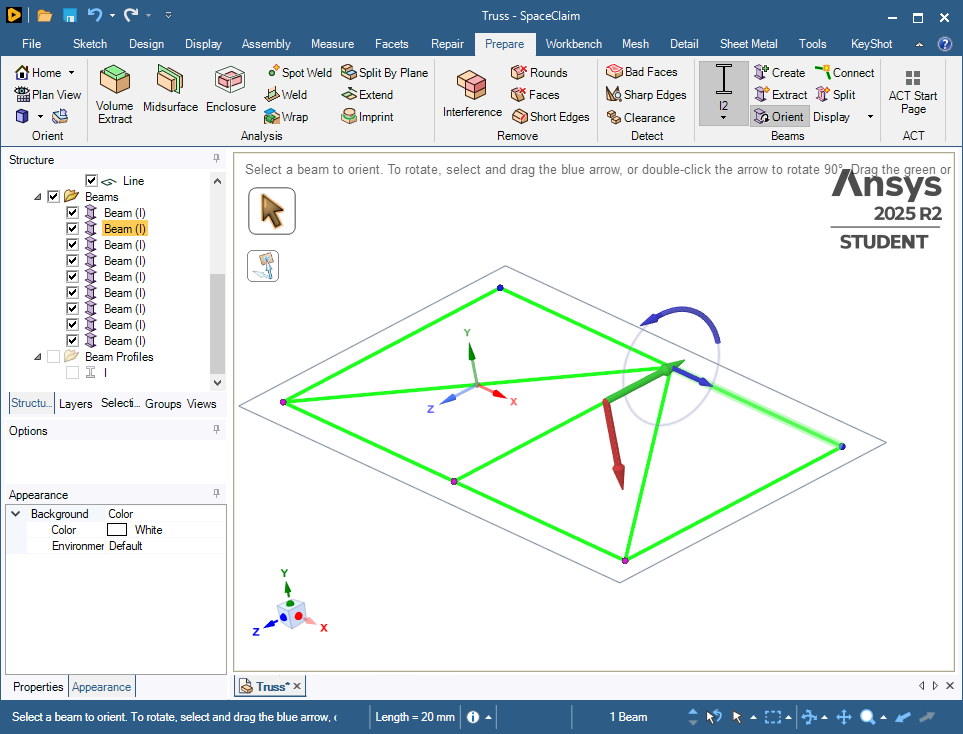
      Go back to the Prepare tab and click the Orient button if any of the beam cross-sections are not oriented the way you want.

      In Mechanical, on the Display tab, turn on Thick Shells and Beams to see the I beam profile orientation.

      • 1260960796
        Subscriber

        How elaborate! But, I'm a scholar who are building a solid model for thermal analysis, so I have some little questions yet.
        1) I found that it's not a solid model, right?
        2) Can I muti-select(like box selection) lines? Because the actual bridge model is much more complex, it's impossible to choose the lines one by one.
        3) As the last figure you posted shows, model is disconnected at the corners(Figure 1). But it's continous when I use "Pull" function(Figure 2). So, how can I connect it?

    • peteroznewman
      Subscriber

      1) Yes, a beam model is not a solid model. 

      3) The beam elements are connected at the ends. What you are seeing above is the representation of the cross-sections that are used in the calculation. Beam elements are useful for Static Structural analyses.  This image is the deformation of the beams after applying a force to the truss.

      Beam elements are a problem in Thermal models as they can’t be used in Convection boundary conditions.

      If there are so many lines in the bridge, I expect meshing a solid model will not go well because of the high aspect ratio of truss member length to web thickness dimensions.

      Have you considered shell elements? They are useful in both Thermal and Structural analyses.

      • 1260960796
        Subscriber

        Thanks a lot for your patient reply. 
        According to your description, everything makes sense because of beam elements instead of solid ones. I feel so pity that we can’t bulid a solid model by using such a useful function —— specifying cross-section, but “pull” function can. However, using “pull” I need to draw lots of the same cross-section repeatedly in a plane perpendicular to the splines, seems inefficiently, I think. I don't believe that developing the function of creating a solid model by specifying cross-section is hard for ANSYS, Inc. Looking forward to improvement!

    • peteroznewman
      Subscriber

      Ansys SpaceClaim has a Python scripting capability. A SpaceClaim file has a collection of 3D lines in a document and a surface that represents the cross-sectional face for a sweep operation. Show the outline of a script that copies that surface to a plane normal to one end point of each line and sweep that face along each line to create solid geometry.

      Here is the ChatGPT response to that query.  I have not tested the code that ChatGPT came up with, I doubt it works as is, but you can see that you could write a script to programatically do the sweep operation on every line in the document because as you say, there are too many lines to do manually.

      Though this may give you what you are asking for, I believe that when you try to mesh such a solid, you will be disappointed when the mesher fails to fill that solid body with elements as happened in this discussion: https://innovationspace.ansys.com/forum/forums/topic/declining-temperature-where-the-temperature-should-only-increase/

      I believe your best path to a successful thermal analysis is to extrude lines representing the cross-sectional shape (not a surface) to create zero thickness surfaces along each trajectory. This could also be automated using a script to do thousands of lines. These surface will be meshed with shell elements that the mesher will be far more likely to mesh successfully compared with the solid model described above.

Viewing 4 reply threads
  • You must be logged in to reply to this topic.