
-
-
September 1, 2021 at 4:56 pm
shubhamop20
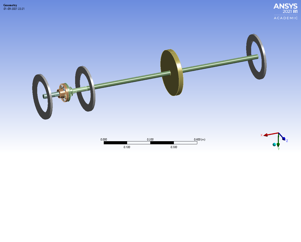
SubscriberI am performing a shaft misalignment study. I have attached my setup. I have used standard bearing connections at 3 places for support.
I have the following questions:
1) The image shown below is a zero misalignment system. Now I want to provide misalignment of, say, 0.2mm. How can I incorporate this in Ansys?
2) Do Ansys have the feature to provide offset in the bearings, or do I have to provide the offset in the cad model itself?
September 2, 2021 at 2:55 amBenjaminStarling
SubscriberJust to confirm my understanding, you would like to analyse the misalignment between the bearings? Are you also checking the alignment of the bolted connection?
To model the misalignment of the bolted connection you can either move the geometry in CAD, or use a part transform. You can also use the contact properties "Interface Treatment" and "Offset" to simulate extreme misalignments which require the bolts to take up a shear load to bring the misaligned parts together.
For the bearings the mobile location can be changed, however, this does not accurately capture any preload on the bearing caused by the misalignment. The COMBI214 Bearing element can be replaced with a series/parallel of springs and dampers, this requires a lot more user input and model building, but allows for initial preload on the springs which can help to model misalignment issues (see COMBI1N4).
The bearing connection you see in graphics is just an annotation, you can decrease it's size by zooming in and hitting Display-> Rescale, or you can turn off the bearing annotation in Display-> Preferences.
September 2, 2021 at 8:47 amSubscriberThanks a lot, Benjamin for helping. As you said, I think the best way would be to provide the offset in the coupling itself directly.
****Can I apply a rotating load or unbalance on the disc in transient structural, or I have to replace this disc with an eccentric disc. ***
My ultimate aim is to collect time-series data for different shaft misalignment values. The literature says that unbalance will trigger the response at 1X and misalignment at 2X of the operating speed. I want to reproduce this result.
So for the dry run, I am expecting a 1X component in the frequency response(unbalance). And a 1X and 2X component in the presence of misalignment.
****Also, what should I do to rotate the setup I think rotational velocity doesn't rotate the setup. It just applies the inertial load, so adding a point mass will not help to produce an unbalance.
Should I apply a torque or something? What's your take on this? ****
Viewing 2 reply threads- The topic ‘Shaft misalignment in coupled rotor system’ is closed to new replies.
Ansys Innovation Space Trending discussions
 Top Contributors
-
peteroznewman
 3215
3215 -
javat33489
 1031
1031 -
scabo
 968
968 -
Shyam Prasad V Atri
 859
859 -
adib.aktab999
798
Top Rated Tags
© 2025 Copyright ANSYS, Inc. All rights reserved.
Ansys does not support the usage of unauthorized Ansys software. Please visit www.ansys.com to obtain an official distribution.
-


The Ansys Learning Forum is a public forum. You are prohibited from providing (i) information that is confidential to You, your employer, or any third party, (ii) Personal Data or individually identifiable health information, (iii) any information that is U.S. Government Classified, Controlled Unclassified Information, International Traffic in Arms Regulators (ITAR) or Export Administration Regulators (EAR) controlled or otherwise have been determined by the United States Government or by a foreign government to require protection against unauthorized disclosure for reasons of national security, or (iv) topics or information restricted by the People's Republic of China data protection and privacy laws.


