-
-
November 6, 2025 at 4:32 pm
a.kanthale
SubscriberHello all,
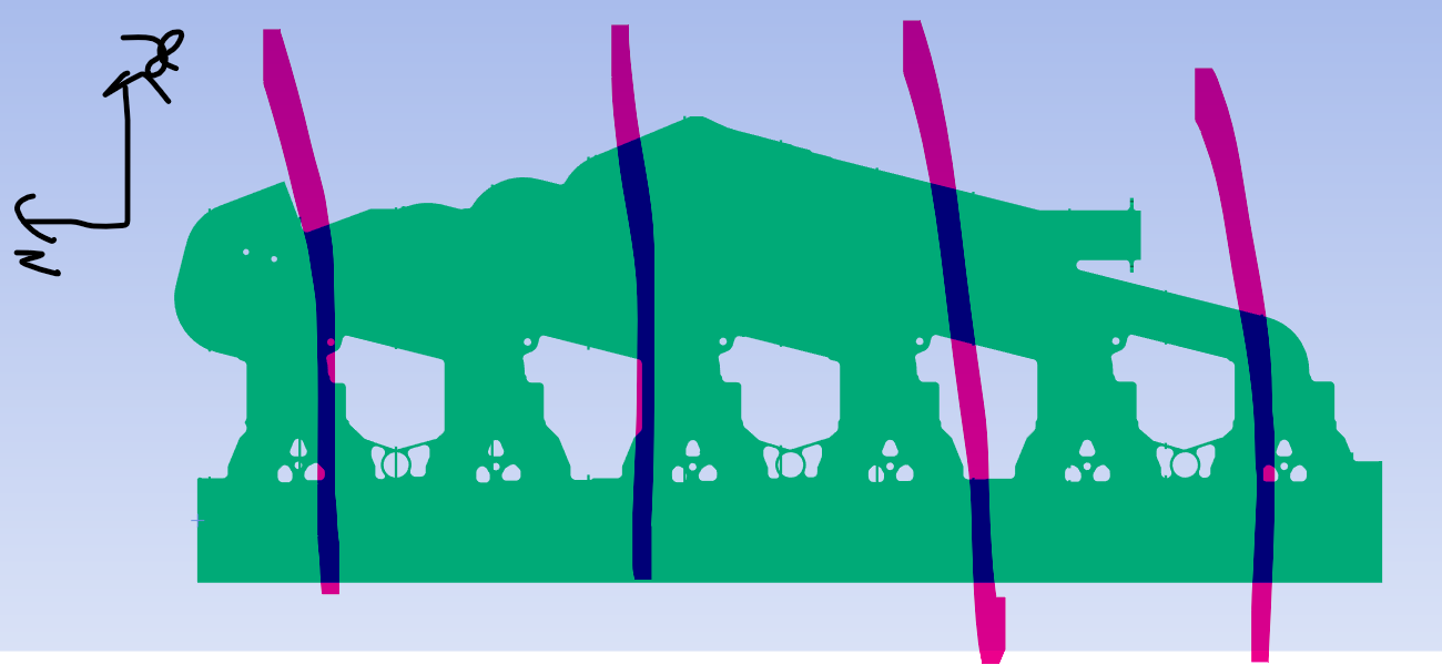
I'm working on a complex part that undergoes thermal analysis cooling from 700 °C to 50 °C, followed by a transient structural simulation to study quenching effects and shrinkage. The part rests on rods with no constraints—only gravity acts in the -Y direction. I want to avoid modeling the rods to save time. In reality, the part bows, but I’m unsure what boundary conditions to apply to prevent rigid body motion and capture the bowing behavior. The part lies in the XZ plane.
-
November 7, 2025 at 8:33 am
Sourabh Upadhyay
Ansys EmployeeHi,
I think you can use 3-2-1 rule to constrain the model for preventing rigid body motion. Please refer: (2) Understanding the Need to Fully Constrain the Model Using Ansys Mechanical — Lesson 2 - YouTube (time stamp = 10:47))
-
November 7, 2025 at 8:47 am
mjmiddle
Ansys EmployeeYou should split the faces along vertical lines where your bars would be. Select these edges and set a displacement that sets y=0 and leaves the other directions free. You can also set a remote displacement on a vertex that sets x,z=0 and ry=0. Or instead of a remote displacement, you can use a regular displacement on one vertex that sets x,z=0, and then another displacement on another vertex that is along the x direction from the previous vertex and set z=0.
-
November 7, 2025 at 9:24 am
peteroznewman
SubscriberIf the part is made from a single isotropic material and no constraints prevent thermal strain, the part will be slightly larger at a uniform temperature of 700 C compared with a uniform temperature of 50 C, but the temperature would not cause it to bow.
Gravity and contact with the the supports in the Y direction would cause bowing. If you have temperature dependent Young’s Modulus, there may be more bowing at 700 C compared with 50 C assuming the material is less stiff at higher temperatures.
If there are exactly 3 support points, you can use a simple 3-2-1 displacement constraint pattern on the 3 contact points that create a triangular base of support. An example is X,Y,Z=0 on one point, Y,Z=0 on a second point some distance along the X axis from the first point and Y=0 on a third point some distance along the Z axis from the first point. This is called a Kinematic Mount or Exact Constraint pattern and allows for a stress free themal expansion/contraction of the part in a linear analysis.
If you have more than 3 support points, then use nonlinear contact and let the solution determine how the part will contact the points.
-
November 7, 2025 at 1:53 pm
dlooman
Ansys EmployeeThere's also the option of "Weak Springs"
-
- You must be logged in to reply to this topic.


- LPBF Simulation of dissimilar materials in ANSYS mechanical (Thermal Transient)
- Convergence error in modal analysis
- APDL, memory, solid
- Meaning of the error
- How to model a bimodular material in Mechanical
- Simulate a fan on the end of shaft
- Nonlinear load cases combinations
- Real Life Example of a non-symmetric eigenvalue problem
- How can the results of Pressures and Motions for all elements be obtained?
- Contact stiffness too big

-
4177
-
1487
-
1363
-
1194
-
1021

© 2025 Copyright ANSYS, Inc. All rights reserved.


