TAGGED: dpm, periodic-boundary
-
-
October 14, 2025 at 8:49 pm
sjohn
SubscriberMy case is similar to Chapter 2: Modeling Evaporating Liquid Spray in the Ansys Fluent Tutorials, with the following notable exceptions.
- Instead of a an air-blast atomizer, the injection is performed using a pressure swirl atomizer.
- Periodic boundary condition: Instead of 30-degree wedge, my case has a 22.5 degree wedge as the domain.
- Instead of swirling air, air is introduced parallel to the main axis.
For the pressure swirl atomizer injection properties, I have specificd the azimuthal start and end angles as 0 and 22.5 degree. Despite this, the display shows a 360 degree cone and the droplets are sprayed outside the domain (22.5 degree wedge). When I run the case, I also get an error saying the droplets were sprayed outside the domain. -
October 15, 2025 at 9:05 am
Rob
Forum ModeratorThe injection display is "dumb" in that it's just a graphic and doesn't reflect any angle settings - it's an aid to make sure you've got the injection in the right place and point in the right direction. Assuming the sector modelled is 0 to 22.5 degrees and not 90 to 112.5 or similar try reducing the band to 0.5 to 22.0 and see if that changes. Any parcels that miss the domain are automatically fail. It should be a warning rather than an error, and should also show a fraction of mass/parcels that are missing.
-
October 15, 2025 at 2:38 pm
sjohn
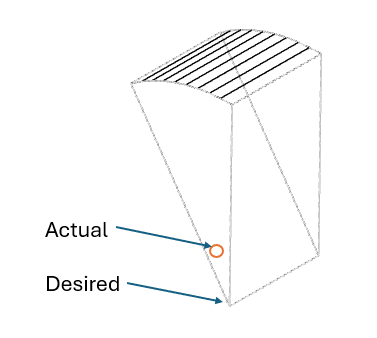
SubscriberI was able to solve this issue by moving the injection point slighly into the domain. Initially, I had set the injection point at one of the vertices of the wedge but it gave me the warning (as mentioned in my first post). When I ran the case after moving the point into the domain, it did not give me a warning but the position of the injection point does not accurately represent my test article because it is not at the vertex (desired) but inside (actual) as shown in my schematic below.
-
October 15, 2025 at 2:42 pm
Rob
Forum ModeratorIf it's precisely on the vertex it may be "outside" due to rounding effects. You should be fine if it's a tiny amount into the first wedge cell. I've seen similar problems on circumferential injections where the defined point is on the curved face but fractionally outside the faceted representation of the curved face.
-
October 15, 2025 at 3:22 pm
sjohn
SubscriberThe issue with my current apporach is that it models an injection point in one wedge, which due to the periodic condition causes there to be multiple injection points. In reality there is a single pressure swirl atomizer at the center (vertex), which sprays fluid into each wedge. This should be a common scenario, wonder how is such a case setup.
-
October 15, 2025 at 3:59 pm
Rob
Forum ModeratorIf you set the injection with a full 360 cone what happens? Make sure you've got more than 64 streams to ensure there are no half-angle effects for parcel injection placement.
-
October 15, 2025 at 11:34 pm
sjohn
SubscriberMy guess is that an injection with a full 360 degree cone would give warning similar to the case in which the injection point was at the vertex and the cone was 22.5 deg (difference between azimuthal start and end angles).
I am using 16 streams total because there are 16 sectors (wedges) of 22.5 deg in reality. I figured it would be good to have only one stream in each sector/wedge. The flowrate specified by me in Injection Settings/Point Properties is 6.88e-05 kg/s.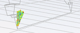
Can you explain the significance of 64 streams?
-
October 16, 2025 at 9:14 am
Rob
Forum ModeratorWith a 22.5 degree sector it's possible for the start/stop angles and 16 streams to hit one or other side of the sector, similarly 32 could hit both. When we get to 4 streams per sector it's impossible to miss even with a 11.25 degree offset due to any oddities in the domain orientation.
I have used (abused) the cone injections in a similar way to get spray into larger chamber, that may be a better option. You may need to use a UDF for inlet angle/speed as Expressions aren't fully implemented on the Injection panel at 25R2.
-
October 16, 2025 at 2:21 pm
sjohn
SubscriberThanks for the explanation. Yesterday, I had started a new case with 64 streams total and ran it overnight. This morning I found that it had diverged after 0.277 ms of flow time (step size was 1 microsecond).
My earlier case with 16 streams total had run for 0.232 ms of flow time (step size was same). This case had not diverged but I had stopped it so that I could run the 64 stream case.
I am tacking particle with fluid flow time step and using unsteady particle tracking. The interaction with continuous phase is on and the DPM sources are updated every flow iteration. The DPM iteration interval is 1. I beleive these settings are conservative.
The total cells in my domain are 572396. The mesh type is polyhexcore with three boundary layers. The rate of growth is 1.05 for all mesh elements. The average orthogonal quality is 0.96, while the min. is 0.27. The max skewness and max aspect ratio for the surface meshes are 0.58 and 18, respectively. These were obtained after surface and volume mesh improvement steps.
After the droplets evaporate, they release single species, which react with a species from a separate inlet flow. The single volumetric reaction is set to Finite Rate and solved using the stiff chemistry solver. All species and the kinetic parameters for the reaction are from Fluent database. For both cases (16 and 64 streams), I see an increase in temperature and heat of reaction indicating reaction is occurring.
For the outlet boundary condition, I have set gauge pressure to 0 psi and checked prevent reverse flow. The operating pressure 14.7 psi.
I had run a steady state simulaiton without DPM and just multi-species gas flow and no reactions and the case had converged within 250 iterations.Is there anything that could be improved to prevent divergence?
-
October 16, 2025 at 2:26 pm
sjohn
Subscriber -
October 16, 2025 at 3:45 pm
Rob
Forum ModeratorPreventing back flow tends not be a good idea unless you can identify why you're getting back flow. It's one of those options that was added but can lead to problems later on.
Stability could be linked to evaporation rate (I assume it's exothermic) and/or mesh resolution amongst other things. The cell metrics tell us the cells are OK, but not whether you have enough of them to resolve the gradients in the domain. Pictures may help: plot with node values off to remove the contour smoothing.
-
October 16, 2025 at 4:05 pm
sjohn
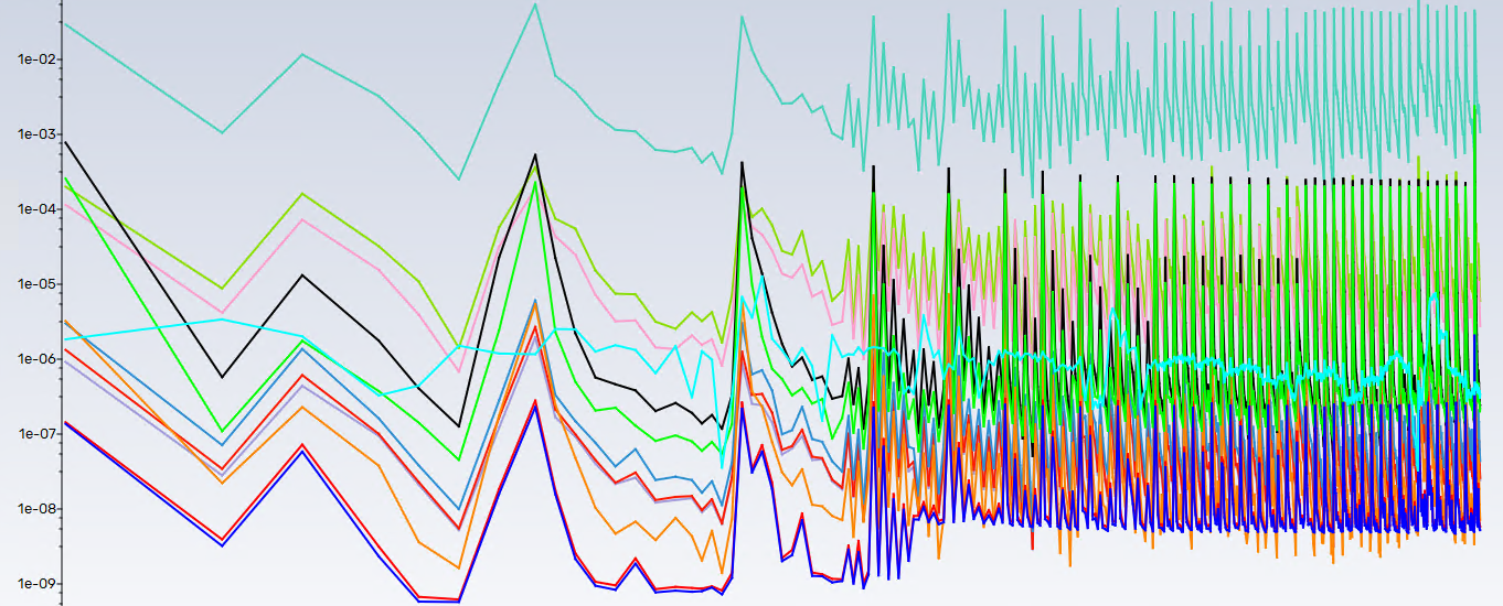
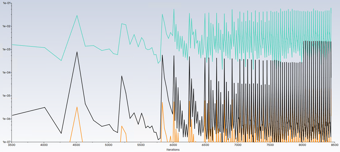
SubscriberI have restarted the 16 stream case and the residual (black) for the species involved in DPM, evaporation, and reaction (reactant) rose abruptly. Similar abrupt change was seen in one of the products. These trends may simply indicate that appreciable reaction is occuring as more reactant mass is spray into the domain. The contiuity residual (teal) started climbing but still would drop below 1e-03. In response, I reduced the time step from 1e-06 to 8e-07. The energy residual (organe) still continues to drop below 1e-06 at every time step. (I am not using residuals as convergence criteria similar to the tutorial example on modeling evaporaing liquid spray).
-
October 16, 2025 at 4:09 pm
-
October 16, 2025 at 4:14 pm
Rob
Forum ModeratorHow are the velocity, temperature and species concentrations looking?
-
October 16, 2025 at 4:38 pm
-
October 16, 2025 at 5:56 pm
sjohn
SubscriberThe spatial discretization for the species is second order upwind and the associated under-relaxation factors of the species is 1. Do I need to reduce the URFs to improve the drop in residuals per time-step?
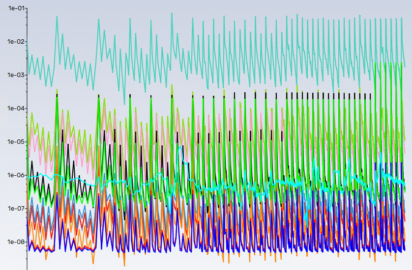
In the plot below, x-axis is from 8000 to 10000 iterations. Teal- continuity, black -reactant species, green-product species, light green - k (turbulence), pink-omega (turbulence).
-
October 17, 2025 at 8:47 am
Rob
Forum ModeratorResiduals are a useful tool, but I'd always look at the flow field too. A time step of 1s is perfectly fine in one model, whereas 1e-9s is required in another so that's "just" a setting rather than being a sign it's working. I'd also always make sure I did 3-4 iterations per time step now too - that usually means the solver can't just jump through a time step because the convergence criterion were hit too early.
-
- You must be logged in to reply to this topic.


- air flow in and out of computer case
- Varying Bond model parameters to mimic soil particle cohesion/stiction
- Eroded Mass due to Erosion of Soil Particles by Fluids
- I am doing a corona simulation. But particles are not spreading.
- Centrifugal Fan Analysis for Determination of Characteristic Curve
- Guidance needed for Conjugate Heat Transfer Analysis for a 3s3p Li-ion Battery
- Issue to compile a UDF in ANSYS Fluent
- JACOBI Convergence Issue in ANSYS AQWA
- affinity not set
- Resuming SAG Mill Simulation with New Particle Batch in Rocky

-
4102
-
1487
-
1318
-
1156
-
1021

© 2025 Copyright ANSYS, Inc. All rights reserved.

