TAGGED: taper, transmission
-
-
August 5, 2022 at 7:54 am
shawn
SubscriberI am working on a simulation (varFDTD in MODE) of a taper structure (see the attached schematics) to calculate the loss. But I found something weird.
I use a mode source in the simulation. However, the transmission spetrum (see the attached figure) at the output (green line) is greater than that at the input port (blue line), which from my perspective is not reasonable.
I have tried several ways, e.g., increasing simulation time, the number of the PML layers and the mesh accuracy to deal with this issue, but all in vain. Is there any idea to solve this issue?Â
Let me know if more detail is needed.
Here are some screenshots of the settings in the simulation.
Â
-
August 5, 2022 at 8:25 pm
Guilin Sun
Ansys EmployeeYou may need to do the following modifications:
1: significantly increase the mode source size, not to truncate the field amplitude
2: for the input and output waveguides, since they are straight, you only need to simulate half wavelength or shorter.
3: make sure the mode is what you need. Please check its polarization
4: make sure the green reference point is inside the waveguide.
Please try again. This structure should not have strong resonance, so autoshutoff min 1e-5 and simulation time1000fs of the default values should be sufficient.Â
-
August 8, 2022 at 9:35 am
shawn
SubscriberThank you for the reply!
I have tried to improve the simulation based on your suggestions. As you can see in the attached screenshot below, the span of the mode source is significantly increased and extended beyond the boundary of the varFDTD region. And the mode I selected in the mode source is just the fundamental TE mode. Unfornately, the output transmission is sometimes greater than the input one (since it becomes sinusoidal), alothough the difference is quite small.
I also check the field profile (see the figure below) at the input and output monitors and the fields look fine and not truncated.
And I found that increasing the distance between the boundary of varFDTD region and the output monitor at the right hand side will let shape of the output transmission spectrum less sinusoidal. So I am not sure if this indicates that the simualtion region should be much larger than that you suggested in point 2?
-
- The topic ‘
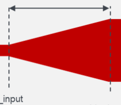
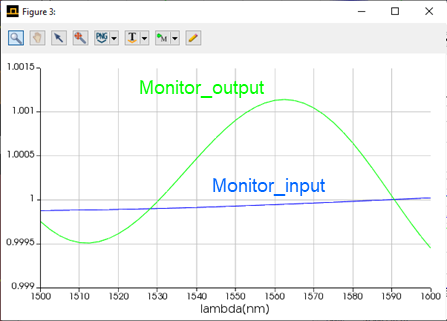
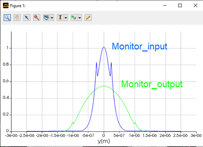
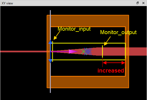
output transmission is greater than input transmission in taper structure’ is closed to new replies.
-
3327
-
1042
-
1017
-
865
-
826
© 2025 Copyright ANSYS, Inc. All rights reserved.