-
-
November 21, 2024 at 11:01 am
m.t.vu
SubscriberHi all,
I have been trying to reproduce the results of this paper: "Comparative analysis of hydrogen/air combustion CFD-modeling for 3D and 2D computational domain of micro-cylindrical combustor" but I am nowhere close of getting the same results. (I'm not sure whetehr I am allowed to post the paper in here, so for now I will not do that, unless given permission).
The geometry is shown as follows:
For this, what is given is that this is a hydrogen-air combustion.
The following assumptions were given: The heat transport and body force caused by concentration gradients can be neglected due to its low value. Moreover, other assumptions are taken for CFD-modeling: steady-state conditions of combustion; no the flux of energy due to a mass concentration gradient (no Duflor effects); work by viscous forces and by pressure is not done; surface oxidation reactions of the metal wall are absent.
I do not think I have to adjust anything in Fluent with these assumptions.It uses the Eddy Dissipation Concept model. No values were given in here, so I kept the default values.
The RNG k-epsilon was used, the constant values which were given here were C1 and C2, which were kept at the default values as well.
P1 was used for the radiation model.The specific heat and density were determined by the equations of mixing-law and incompressible-ideal-gas law.
The viscosity is determined by Sutherland viscosity law, however, these values were not given.
The thermal conductivity is computed as average mass fraction of each element, I assume this could be doen with the mass weighted mixing law.
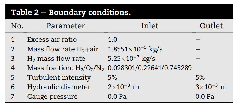
The pressure-based solver was used and the convergence criterion were set to the correct values as well.This were the given BCs:
I ignored the excess air ratio and the H2 mass flow rate, since I was not sure where to put these.
I entered the mass flow rate H2+air for the mass flow rate in the inlet. I was not able to enter the N2 mass fraction, but while double checking the results, the mass fraction of this seemed correct (it probably automatically entered this after I filled in O2). For the outlet I have tried both the pressure-outlet and outlet-vent (so I was able to put the hydraulic diameters and turbulent intensity in there). It was not specifically mentioned which one was used. For the wall, steel was used and I kept everything else at its default values, since nothing was mentioned furthermore.
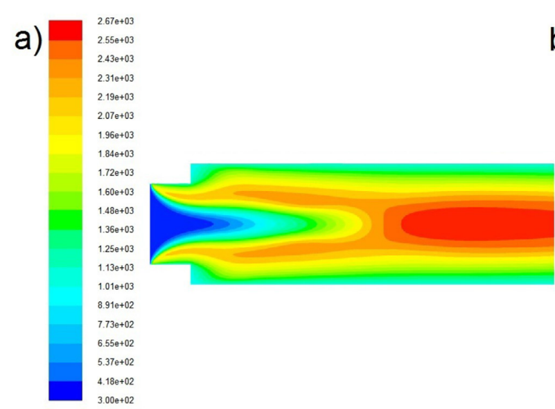
For the axisymmetric simulations, these were the results:
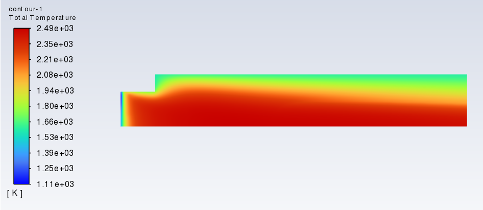
Figure 1 is the paper, figure 2 is my result.
For some reason, in my simulation the temperature starts around 1100K, while I put 300k for the inlet. Also can be noticed that the wall temperature is much bigger and that the temperature increases very quickly from the start, compared to the paper.
Does anyone have an idea what I am doing wrong in here?
-
November 21, 2024 at 11:53 am
Rob
Forum ModeratorAssuming your species mixture is H2, O2, H2O and N2 in that order N2 would be whatever isn't the others because of the way Fluent handles species.
Excess air will be a combustion note, but as the mass flows are then given isn't needed in the set up: you need to do some reading on combustion chemistry.
P1 isn't really useful for hydrogen flames, so you may want to review the other options. If the paper is older then it may have been used because of the lower computational cost.
I can't see any chemistry or material values in what you posted: how did you determine these?
-
November 21, 2024 at 11:57 am
m.t.vu
SubscriberThe values of the materials were given by Fluent itself already, I did not adjust these. It had options to use a constant value or to use the mixing law, which I chose based on what was given in the paper.
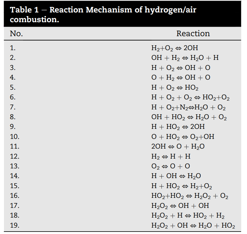
For the mechanism, this was used:
When I'm running this simulation, it gives me a dasac failure which goes away eventually, but the results still seem odd (as shown in the picture before)
-
November 21, 2024 at 4:43 pm
Ren
Ansys EmployeeThe geometry dimensions look quite small. Did you check the Reynolds number to see if the flow is turbulent? Maybe it is not.
The Eddy Dissipation Concept (EDC) combustion model is for turbulent flames. If the flow is laminar, then you need to use the "Finite-Rate/No TCI" option.
The 1st plot is most likely showing static temperature but you are plotting the total temperature.
The 1st plot seems to indicate that the chamber walls are cooled. Please check the paper.
Is the calculation converged? Please check the residuals values, global heat & mass balance using flux reports.
-
November 21, 2024 at 5:24 pm
m.t.vu
SubscriberThe paper was using a turbulent flame, hence the EDC combustion model was used (and therefore I have been using the RNG k-epsilon model as well instead of the laminar one). I forgot to mention that the unit is mm (which is indeed small). I looked at both the static and total temperature, but both did not show much difference.
The only things mentioned about the wall is that it is made of steel and that surface oxidation reactions of the metal wall are absent.
The calculation was not converged, but the result did not change when I went from 510 iterations (which would show a convergence according to the paper) to 5100 iterations.
The thing that confuses me the most is that the results don't even look slightly close to the results of the paper, while I have tried to remake this multiple times and it keeps giving me the same result. Is there any way for me to post the paper in here to see if you can see the difference from what I have done?
-
-
November 22, 2024 at 11:37 am
Ren
Ansys EmployeeIs your model planar 2D or 2D-axisymmetric? How does this compare with the paper? Your temperature plot suggests that the flow velocity is too low so that the flame is flashing back to the inlet.
-
November 22, 2024 at 11:51 am
m.t.vu
SubscriberThe model is axisymmetric, which is also the case in the paper. For the inlet, I have added a massflow inlet, which is set at 1.8551e-5 kg/s. I am not sure whether I also can have a different velocity in there? The paper does not mention anything else than the massflow inlet, as shown in the main picture.
-
-
November 22, 2024 at 11:38 am
Ren
Ansys EmployeeYou can't post the publication document itself but please post the reference here.
-
November 22, 2024 at 11:53 am
m.t.vu
SubscriberThe paper is:
Comparative analysis of hydrogen/air combustion CFD-modeling for 3D and 2D computational domain of micro-cylindrical combustor
by
Dmitry Pashchenko.
https://doi.org/10.1016/j.ijhydene.2017.10.070
-
-
November 22, 2024 at 4:29 pm
Ren
Ansys Employee1. Can you show me a velocity contour plot, and in particular, what is the velocity in the region next to the inlet?
2. How did you "ignite" the mixture?
3. What is the thermal condition applied at the wall boundary?
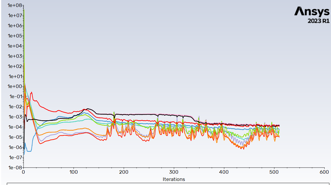
4. Could you post a residuals plot?
5. Please show the flux reports for mass flow rate and total heat transfer rate (either screenshots or the text output from Fluent).
-
November 23, 2024 at 12:39 pm
m.t.vu
Subscriber1)
The velocity at the very inlet is 0 m/s, which already seems very odd. Especially since the mass flow rate is 1.8551e-3 kg/s at the inlet.
2)
I did not add anything specific to ignite it (did not patch it or anything). I filled in the model, BCs, initialised it and then I ran the simulations.
3)
I have tried both the Heat Flux thermal condition and the Mixed thermal condition. I did not adjust any values in here, except from changing the material from aluminum to steel.
4)
I have tried running it for longer but the results did not seem to change.
5)
"Flux Report"Mass Flow Rate [kg/s]-------------------------------- --------------------inlet 1.8551e-05outlet -1.8556836e-05wall -0---------------- --------------------Net -5.8362543e-09"Flux Report"Total Heat Transfer Rate [W]-------------------------------- --------------------inlet 0.047582231outlet -0.3079085wall -0---------------- --------------------Net -0.26032627
-
-
November 23, 2024 at 2:56 pm
-
November 25, 2024 at 4:12 pm
Ren
Ansys EmployeeThank you for the information.
- the velocity looks wrong if it's zero at the inlet. Anyway, the flame speed of stoichiometric h2-air is about 2.4 m/s. This means that the flame will move upstream. So, it's not possible to get a flame shape looking like that in the paper. A quick calc (with some assumptions) shows that Re = rho*U*L/mu = 1.2*1*0.002/2e-5 = 120. So the flow is probably laminar.
- the EDC model in general will require some kind of "ignition" (either patching or starting from a solution already having a flame). Did you check the temperature field after the initialization?
- The residuals plot does not have a key.
- The mass balance is good but the heat fluxes look very unbalanced.
- Did you check if the parameter values for the Sutherland viscosity actually make sense?
-
November 25, 2024 at 5:08 pm
m.t.vu
SubscriberSo if I understand correctly, the flame shape in the paper is incorrect? I was running some other simulations and got this (which I had shown earlier):
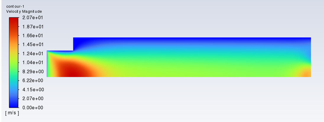
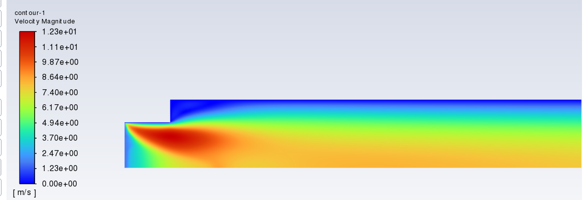
Does this seem more logical than the one in the paper? The velocity plot is as follows:
Where it does seem to correspond with the inlet speed that you have mentioned.
I did not check the temparture field after initialisation.
For the Sutherland parameters, I was not entirely sure how to take this on. Since Fluent gave parameters of 0 in the mixture, I had to figure out this by myself. The way I did this was by multiplying the mass fraction of the species (hydrogen and air in this case) by the Sutherland parameters for the individual species (which had values in Fluent).
-
November 29, 2024 at 3:34 pm
Ren
Ansys EmployeeWhat I can say is that the information in the paper is inconsistent to say the least. For example,
The inlet diameter, D = 2 mm, according to the description in the 2nd paragraph in "Numerical Setup". So the inlet velocity can be calculated as:
Density = 0.851 kg/m^3
A = 3.14 e-6 m^2
v_inlet = 1.8551e-5 / (0.851 * 3.14e-6) = 6.95 m/s
The paper has both velocity contour plot and axial profile plot. The inlet velocity can be estimated from the plots to be about 1 m/s, that is very different from 6.95 m/s.
-
November 30, 2024 at 11:38 pm
m.t.vu
SubscriberI think the paper is using an inlet diameter of 4 mm (since that is used in the figure), doing this calculation, this gives an inlet velocity of about 1.7 m/s, which seems to correspond to the plot. So I am not entirely sure whether they made a mistake here besides from mentioning it wrongly in the paragraph.
When I have been trying to replicate the simulation (with the correct viscosity), I keep getting an error on Fluent saying "dasac failure at temperature ..", which could probably be the reason why the results do not seem to correspond. Do you have any idea how I can fix this? All the other settings are the same as I mentioned earlier. This might have caused this issue, but I cannot see what I have done differently from the paper.
-
-
November 29, 2024 at 3:37 pm
Ren
Ansys EmployeeFor viscosity, you can either approximate it using data for air, or use "ideal-gas-mixing-law".
-
December 2, 2024 at 11:19 am
Ren
Ansys EmployeeIf the inlet velocity is 1.7 m/s, then the Reynolds number is even lower. Further, it's very clear from Fig. 13 (and also Fig. 11) that the inlet velocity is not anywhere close to 1.7 m/s. I suggest you contact the author and ask for clarification.
Regarding the flame shape, I think the difference is due to the thermal condition at the walls. You are applying a zero-flux condition. Fig. 7 in the paper shows that the walls are cooled. However the exact thermal boundary condition applied in the paper is unknown.
The message "dasac failure at temperature .." is usually caused by the presence of some excessively large numbers in the chemical mechanism kinetic data. They can be disregarded if the iterations are converging. I don't think this is the cause for getting a different flame shape.
-
December 2, 2024 at 11:52 am
m.t.vu
SubscriberThank you for your response. I have tried to contact the author before reaching out on the forum here, but I still haven't gotten a response.
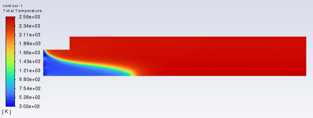
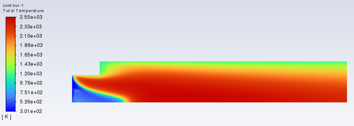
I tried to continue with this by simulating the 2d simulation (before this, I was using the 2d-axis only to see if I could get similar results first before continuing). I kept all the parameters the same (model, boundary conditions), except that this time I made the 2d design planar instead of axisymmetric. This is what the results were for the temperature, which does not have any similarities. The first image is the 2d-axis and the second image is the full 2d geometry.
I have also looked at the velocity:
Where can be noticed that the velocity seems to be very low. Do you have any idea what went wrong in here? The solution was converged, so I was not able to do more iterations for this.
-
-
December 2, 2024 at 1:40 pm
Ren
Ansys EmployeeThe 2d model has a 1m depth. So you cannot use the same mass flow rate because the cross-sectional area is very different. You can try a velocity-inlet boundary and use a velocity same as that in the 2d-axisymmetry model.
-
December 19, 2024 at 5:14 am
ansysadmin
SubscriberHi, what is the kinetic parameters that you have used in the EDC model for the hydrogen combustion reaction?
-
- You must be logged in to reply to this topic.


- JACOBI Convergence Issue in ANSYS AQWA
- Is it able to solve turbomachinery using density-based solver in Fluent?
- Two-way FSI simulation
- Ensight Force_per_unit area_EV
- RIBBON WINDOW DISAPPEARED
- Fluent Meshing Error when .dsco not .stp
- Ansys Fluent for modelling Ocean Wave reactions to Wave Barriers
- Battery Pack cooling
- ISAT ABORT error
- UNASSIGNED INTERFACE ZONE DETECTED FOR INTERFACE…

-
4592
-
1494
-
1386
-
1209
-
1021

© 2025 Copyright ANSYS, Inc. All rights reserved.


