Electronics

Electronics

Topics related to HFSS, Maxwell, SIwave, Icepak, Electronics Enterprise and more.

Non Model Parameters Changing Simulation Results

    • hkowitt
      Subscriber

      I am trying to simulate a 1/4 wave coplanar waveguide (CPW) notch pass filter, that is capacitively coupled to a CPW feedline, both CPW's have 50 Ohm impedence geometry. This is eventually going to be a multiplexing system, where many of these 1/4 wave resonators will act as ways to pick out each individual frequency from the feedline.

      The issue I am having right now is that when I change either the size of my waveports or the frequency range that my simulation is solving over, I get different values for the resonant frequency. Neither the waveport not frequency range are physical things, and as such neither should have an effect on the resonance, but they do. To get to the frequency range, I am going to HFFSDesign-->Analysis-->Setup1 and under adaptive solutions, selecting broadband then defining a range from low to high frequency.


      I have tried changing the following, and have still observed the same behavior of moving resonant frequencies when I change the frequency sweep range:
      -Using Terminal solutions (center conductor as terminal and ground planes as reference for each end of the CPW feedline) vs. using a Modal solution
      -Using discrete vs interpolating sweeps
      -Having my conductors being a sheet vs a 10um thick body
      -Changing max delta S from 2% to 0.5%
      -Changing max allowed number of passes from 6 to 10 to 15
      -Added Curvilinear meshing
      -extended the geometry of the ground planes and transmission line

      Below is an example of what one of the Meshes looks like, the capacitively coupled section of my 1/4 wave resonator is 0.2 mm long:


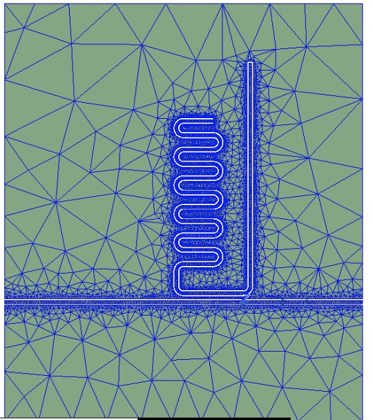
      It seems like the previous results of my simulations are affecting the results of the current simulation. I did 3 different simulations across the same range, all of which gave different results. The following simulations were all done with a broadband adaptive solutions setup from 13.25 to 14.25 GHz, the same maximum number pf passes, same max delta S, all using interpolating sweeps.

      sim1: No resonance, flat S11s and S12s
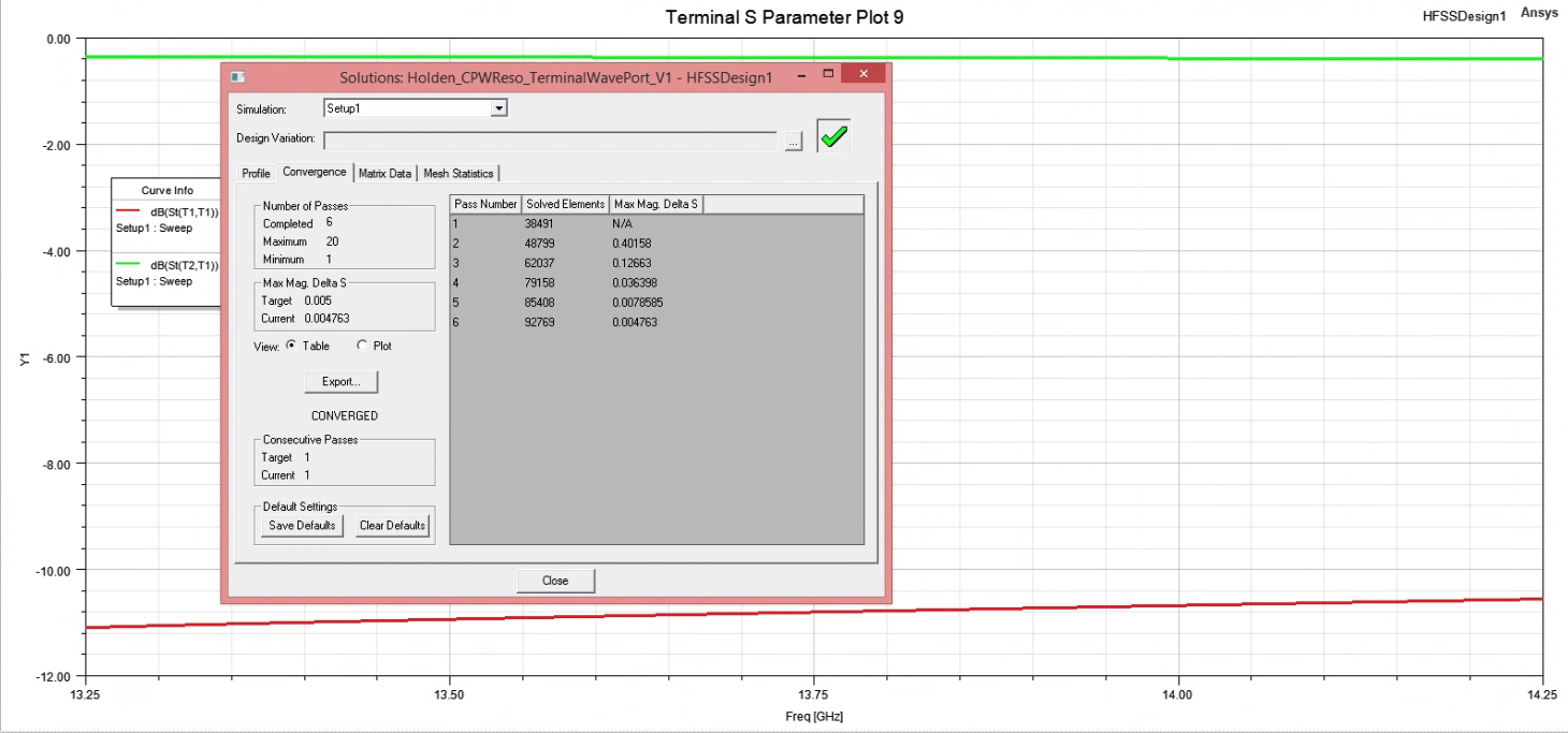
      previous: 13.75 to 14.75 GHz, no resonance flat S11s and S12s


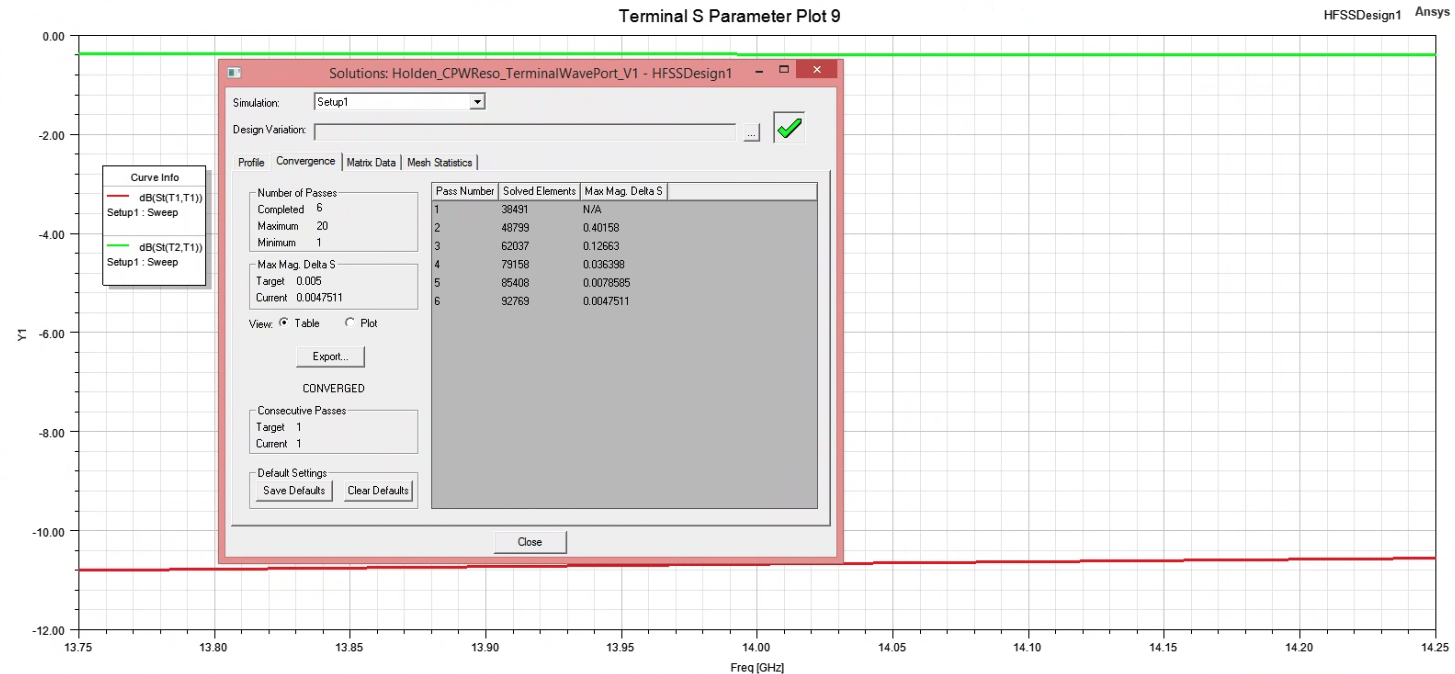
      sim2: -18db resonance depth in S12 at 13.41 GHz
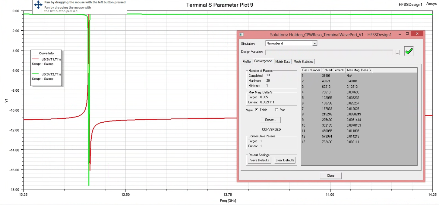
      previous: 13.0 to 14.5 GHz, -1 db resonance depth in S12 at 13.41 GHz


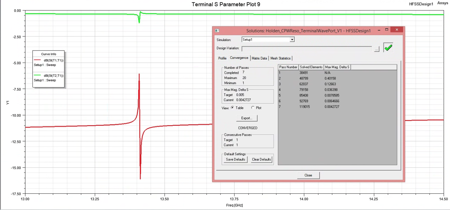
      sim3:-8db resonance depth in S12 at 13.79 GHz
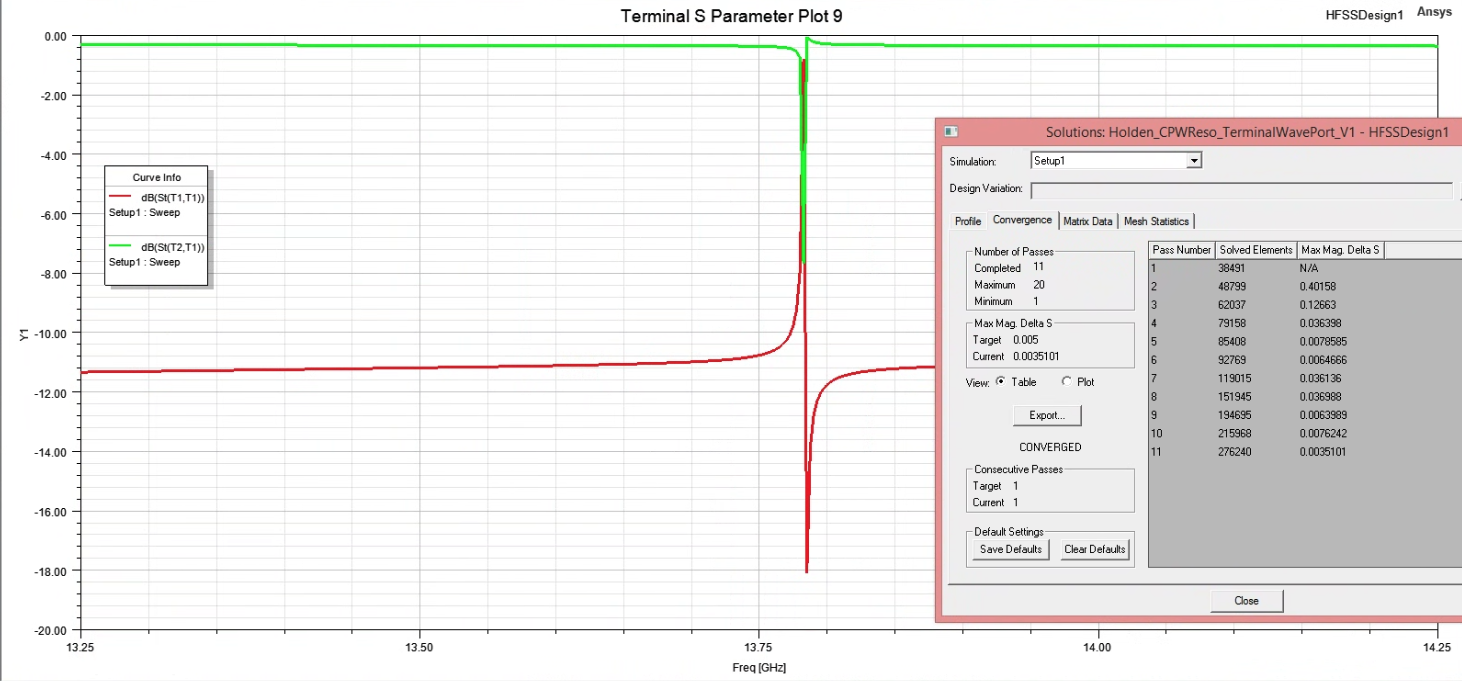
      previous: 13.3 to 13.55 GHz, no resonance flat S11s and S12s  

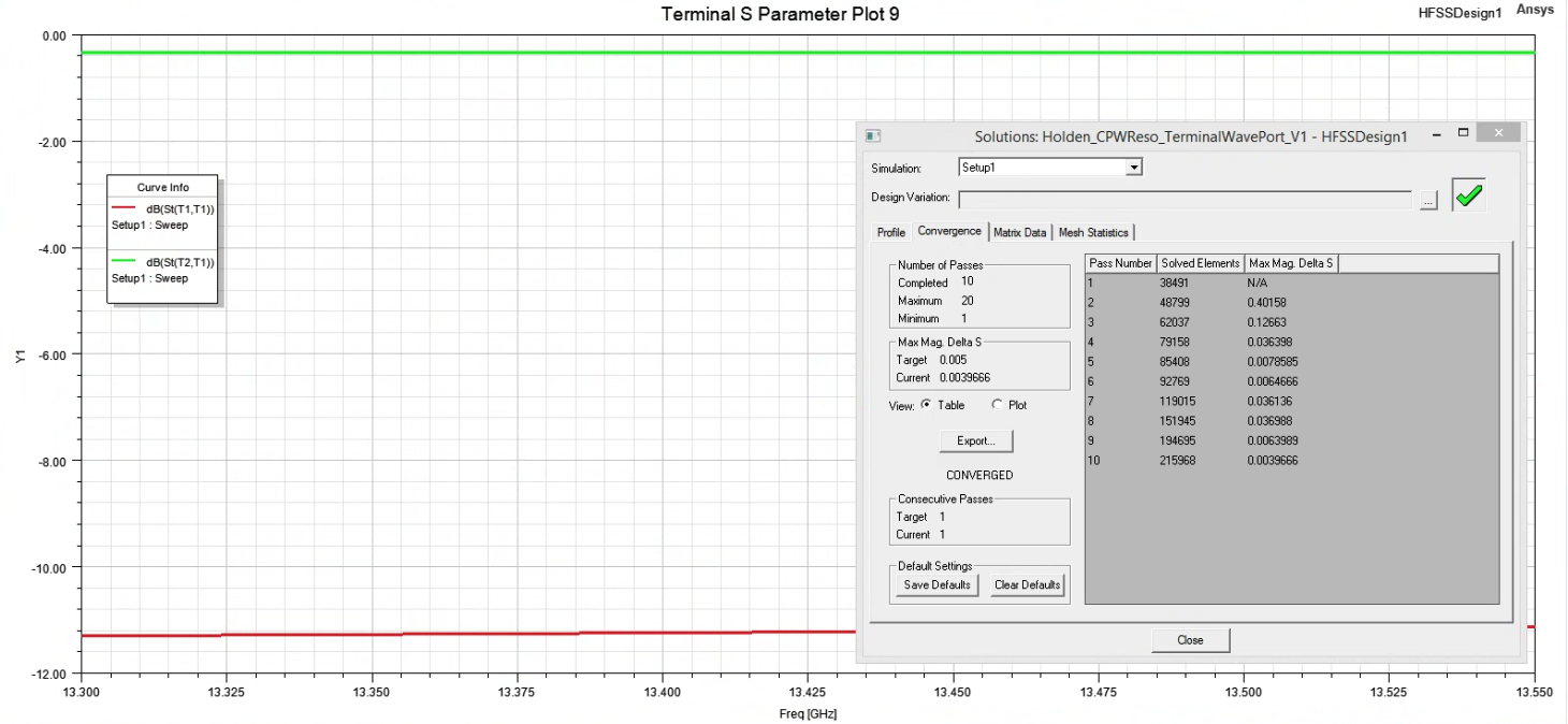
      Another thing, when I do a simulation changing only the frequency sweep range (HFFSDesign-->Analysis-->Setup1-->Sweep and selecting start and end frequencies under frequency sweep), I see consistent results (negligible change by changing frequency range, about 3MHz change by scaling port size by 2x).

      Based on the geometry of the 1/4 wave resonator, I expect resonance around 9.95GHz, however that is far off from what the simulations are seeing. This may be due to a difference in theory vs simulation. Let me know if there are any details I left out that could help solving this issue, any help/suggestions are appreciated!

    • Praneeth
      Bbp_moderator

      Hi,

      Thank you for reaching out to the Ansys learning forum. Your patience is much appreciated.

      Please note that the waveport size should be selected so that the fringing fields are captured for open transmission lines. So, your observation on the change in response is expected. There is a detailed guideline on how to select the waveport size in HFSS help document under section "Wave Port Size".

      Regarding the solution frequency - it is recommended to use the highest frequency in the passband or bandstop as the adaptive frequency for single solution frequency option. You can also use multi-frequency or broardband options if applicable. The response can change if you are not using the optimum adaptive frequency. Based on your results, the S-parameter response does not look normal. I would suggest to check your model thoroughly. You can go through transmission line example designs available through Open Examples > HFSS > Transmission lines.

      Best regards,
      Praneeth,
      Click here to join Electronics Community and build a network
      Introducing Ansys Assistant a 24/7 AI-powered virtual assistant for active Ansys academic customers.

      • hkowitt
        Subscriber


        Hi Praneeth,

        Thank you for reaching out. I updated the port size to match what is recommended in the documentation, and I changed the adaprive frequency to match the maximum frequency of the sweep. I just ran two more simulations from 8-14 GHz and 10-13 GHz, and it looks like the resonance changed from 12.4 GHz to 12.6 GHz going between the two sweeps.

        Also, I am wondering if you have any explanation for the changing resonant frequency on identical sweeps that I mentioned in the original post? In my mind, something must be wrong in the setup for identical sweeps to give different results. 

        As to your comment about the S-parameter response, I believe this is the correct response, due to the resonator being coupled to the feedline. I believe when the frequency on the feedline matches the resonant frequency, the signal gets attenuated into the resonator, which explains a large dip in the S12 across the feedline.

        Best,
        Holden


    • Praneeth
      Bbp_moderator

      Hi Holden,

      Thank you for your reply. My apologies for delayed response.

      I meant to use the highest frequency in the passband of your model as the solution frequency but not the frequency sweep. One more way is to use multi-frequency or broadboand solution frequencies if they are suitable to your model.

      Once the solution is converged for the solution frequency. Then the frequency sweep would be solved using the final mesh at which the convergence is achieved. The frequency response will not change much if the solution frequency is same. Please check one more time.

      In addition, try Fast or discrete sweep instead of interpolating sweep to get more accurate result. 

      Best regards,
      Praneeth.

Viewing 2 reply threads
  • You must be logged in to reply to this topic.