-
-
February 27, 2026 at 9:40 am
shashanksharma3060
SubscriberI need support in creating a geometry for simulating porous media flow through a rock structure that includes fractures/cracks.
Could you please guide me on how to develop such a geometry in ANSYS SpaceClaim? I have attached a similar geometry that was previously simulated in ANSYS Fluent 2022 for reference.
-
February 27, 2026 at 11:42 am
Rob
Forum ModeratorStaff aren't permitted to follow links.Â
Are you wanting flow through the solid parts with porous media and cracks, or just the cracks? How big are the cracks?Â
-
February 27, 2026 at 12:04 pm
shashanksharma3060
Subscriber
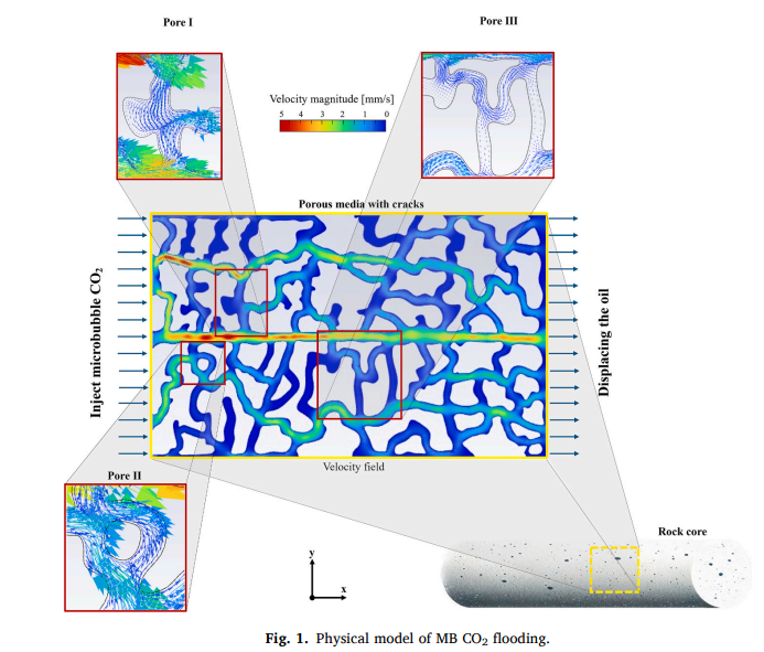
Flow is modeled through the entire pore space, not just isolated cracks. The geometry represents a pore-scale network, where both pore bodies and constricted channels (crack-like features) participate in fluid flow.
The system is not treated as a solid porous medium with Darcy flow, but rather as an explicit fluid domain (void space) where oil and COâ‚‚ microbubbles interact.
Regarding crack size, it does not explicitly define fracture aperture. However, based on:
microbubble sizes (10–90 μm), and
pore-scale geometry,
the effective pore throat/crack sizes are on the order of tens to hundreds of microns, allowing smaller bubbles (10–30 μm) to penetrate while larger ones face restrictions
-
February 27, 2026 at 1:31 pm
Rob
Forum ModeratorAnd you plan on resolving the cracks and bubbles?Â
-
March 2, 2026 at 4:12 am
shashanksharma3060
SubscriberThe study’s idea is to use microbubble COâ‚‚ to suppress flow through cracks (channeling) and improve uniform displacement by controlling bubble-scale fluid dynamics.Â
The paper combines:
Pore-scale numerical modeling
Microfluidic / pore-network simulations
Comparison between:
Conventional COâ‚‚ flooding
Microbubble COâ‚‚ flooding
-
March 2, 2026 at 9:41 am
Rob
Forum ModeratorThat's going to be fun.Â
If you're using micro-CT to get the geometry you'll want to clean up in the segmentation software and potentially refine in Synopsys Simpleware. That will give you a decent tet mesh. Microbubbles aren't going to be easy, so expect a mesh of fairly epic cell count, and some long run times.Â
-
March 2, 2026 at 10:36 am
shashanksharma3060
SubscriberThank you for the guidance.
We understand that micro-CT-based geometry with full 3D meshing (e.g., via Simpleware) can lead to very high cell counts and long computational times, especially when modeling microbubble dynamics.
We are planning to develop a simplified 2D pore-scale model to understand the fundamental flow behaviour, particularly bubble transport, deformation, and interaction with pore throats and fracture-like features.
Could you please suggest:
The recommended approach for generating a representative 2D geometry (synthetic vs slice from micro-CT)?
Suitable multiphase modeling framework (e.g., VOF vs Eulerian) for capturing microbubble behaviour at this scale?
-
March 2, 2026 at 11:03 am
Rob
Forum ModeratorI can't give detailed answers as the Forum is public domain and I'm restricted by the export law rule.Â
For 2d slices a made up geometry is perhaps better if you're planning on running an experiment. Remember in Fluent 2d means it's 1m thick (leave the reference alone) and neglects the "top" and "bottom" effects of surface tension.Â
Micro flows can be problematic because surface tension dominates. So, you'll need a very fine mesh to capture everything. VOF is the only model that can handle micro bubbles correctly: DPM assumes a point mass so you'd have to block it's movement into the porous zones. You may also need to bound the porous zone with a porous jump to handle the VOF free surface calculations. Time step is also going to be VERY small, so if this is a masters project please review with the supervisor as you could be looking at many weeks of run time.Â
-
- You must be logged in to reply to this topic.
-
5274
-
1885
-
1403
-
1262
-
1021
© 2026 Copyright ANSYS, Inc. All rights reserved.
