The first point is that Modal is a linear analysis, so nonlinear contacts such as frictional that work in one direction and not the other, don’t work that way in a Modal analysis. All contacts in a Modal analysis are converted to linear contacts such as Bonded or No Separation.
The second point is that there are no loads in a Modal analysis, so there is no load to cause the inner structure to pass through the metal box.
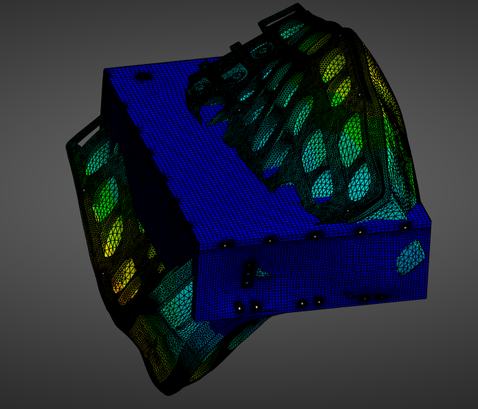
The third point is that deformations in a Modal analysis are arbitrary and meaningless. Only the frequency and mode shape are meaningful.
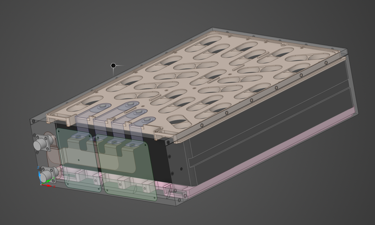
It looks like the metal box has a channel in the side that would allow it to slide into a frame that has a matching guide to limit the motion in all directions except along the channel. I expect there is another feature on the metal box that locks it from sliding along the channel. A more realistic connection to ground is if you delete the Fixed Support on the bottom face of the metal box and replaced it with two remote displacements. One scoped to the top face of one channel and a second remote displacement scoped to the top face of the other channel. If you have a Coordinate System that has X along the channel, Y vertical and normal to the bottom face, then the first Remote Displacement would hold X, Y, Z, Ry = 0 and leave Free Rx and Rz. The second Remote Displacement would hold X, Y, Ry = 0 and leave Free Z, Rx and Rz. Run the Modal analysis on that and request 20 modes instead of 6 and you may see some motion of the metal box.
Modal analysis characterizes how the structure will vibrate if it sees a periodic load. You apply a load to the structure and compute real deformations by using one of the following analyses: Harmonic Response, Random Vibration or Response Spectrum analysis. The product specification generally has requirements for testing the product. For example the spec may say, “product must withstand sinusoidal vibration in three directions with an amplitude of 12 G, over the frequency domain from 20 Hz to 2000 Hz”. That would tell you to do a Harmonic Response analysis.
The Harmonic Response analysis is dropped on the Solution cell of the Modal analysis where you can add an Acceleration load of 12 G in the Y direction. Drop two more to apply loads in the X and Z directions. When those three Harmonic response analyses are complete, you can plot the deformation see if the clearance between the battery pack and the metal box is maintained at a 12 G periodic vibration over the frequency range. The first modal frequency is likely the one where the clearance will be a minimum.
There are many free courses on these topics in the Learning section of this site such as:
https://innovationspace.ansys.com/product/harmonic-response-analysis-in-ansys-mechanical/
https://innovationspace.ansys.com/product/harmonic-analysis-of-structures/
Good luck!
peteroznewman