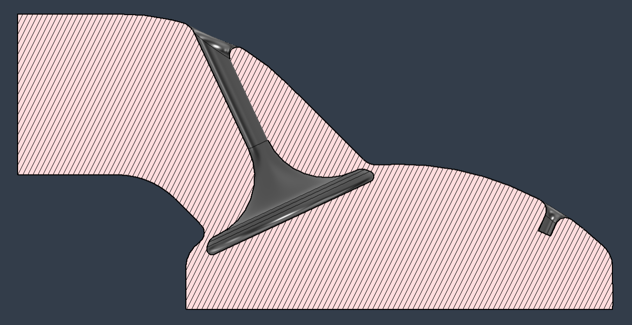
From the current setup, it can be observed that there are a chamber, a valve, an air port inlet, and a fuel port inlet.
The objective of this study is to quantitatively evaluate the mixing quality as air and fuel enter the chamber. To achieve this, I attempted to implement the valve using a UDF with a dynamic mesh. Similarly, I applied a dynamic mesh at the bottom surface, like a piston, to create an expansion effect in the lower region.
For the inlet conditions, I believed that assigning constant mass flow rates for both air and fuel would not be appropriate. Therefore, I implemented UDFs in which the mass flow rates follow a cosine function—starting low, reaching a peak in the middle, and then decreasing again.
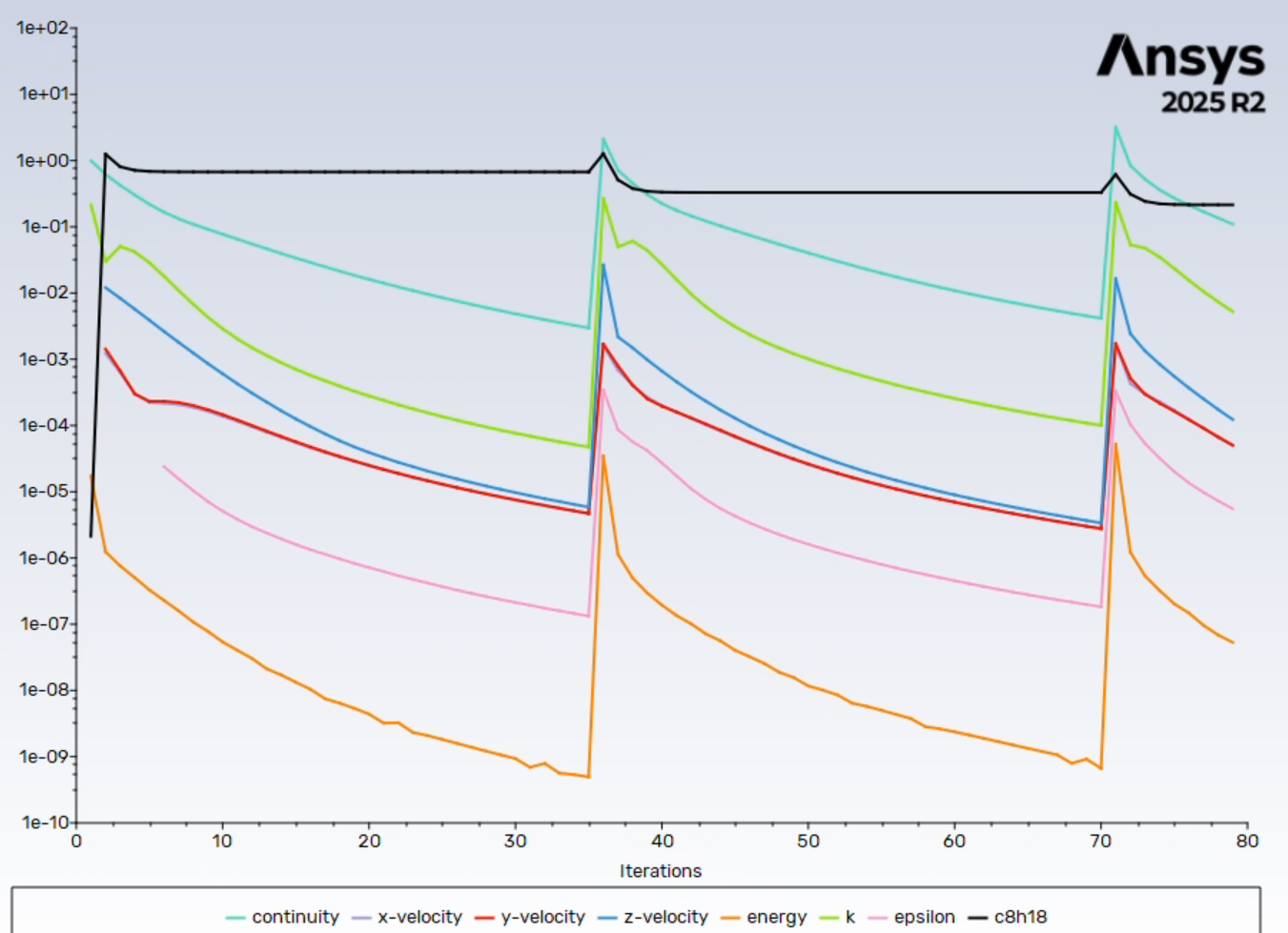
However, when running the simulation with this setup, I observed that the continuity residual increases at every new time step. Although it eventually decreases back to a certain level, it rises again in the next step. This repetitive increase led me to believe that there is a problem.
When I changed the air flow rate to a constant value, the continuity residual stabilized around 1. Based on this, I suspect that the way I implemented the time-varying flow rate using a UDF might be causing the issue.
I would like to ask for your opinion on whether the UDF-based flow rate implementation could indeed be the source of the problem, and how this issue might be resolved.


