TAGGED: #fluent-#ansys, #fluent-#cfd-#ansys, #mechanical-#workbench, 2-way-fsi, ansys-fluent, ansys-mechanical, Ansys-Mechanical-2021-R2, ansysfluent, ansysmechanical, cfd-fluent, fluent, fsi, fsi-2-way, fsi-simulation, fsi-transient, mechanical, system-coupling-transient-structural-fluid-flow-fluent-cfd-post-connector, transient-analysis, transient-structural, two-way-fsi
-
-
September 17, 2025 at 8:59 pm
andres.baeza
SubscriberHello everyone, I have a turbine structure on a fixed pile, both surrounded by water. I was trying to apply a force to the turbine shaft (longitudinal direction) to make the turbine move and then release the force to observe the decay of the oscillation (free vibration). To do this, I plan to use Fluent + Mechanical (Transient Structural) and Ansys Coupling.
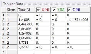
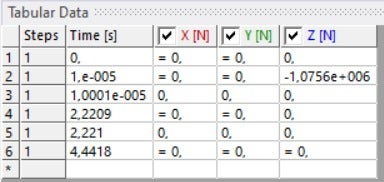
When I used Ansys Transient Structural (without water), I could set the Number of Steps = 2 (see first figure), which allowed me to apply a force for a very short time and then release it at step 2 to generate the free vibration oscillation. However, when I add the "Fluid Solid Interface" (with Number of Steps = 2) in Transient Structural, I see a question mark on this item (within the Ansys Transient Structural outline). This question mark disappears when I return to "Number of Steps = 1." When I try to apply the force and release it with "Number of Steps = 1" (see second figure), I don't get the free vibration oscillation (whether or not I've added the "Fluid Solid Interface").
My question is whether this scenario I've outlined (applying a force parallel to the turbine axis to cause the turbine to move, then releasing the force to initiate free vibration) can be achieved with water (Fluent + Mechanical and Ansys Coupling). Or whether it can be achieved with an initial displacement and then releasing it to initiate free vibration oscillation.
-
September 18, 2025 at 6:31 am
Erik Kostson
Ansys EmployeeĀ
Hi
Ā
Ā
Ā
For reference, the 2 way FSI we should be able to see that (free vib.), but you can only use one step (say apply a short impact load and make sure you have any time steps to capture that).
https://www.youtube.com/watch?v=bP7ZJtdO_Qk
Ā
What are you interested in (say fluid added mass)? In such cases we can use acoustic elements for the water instead of CFD/FSI.
2 way FSI can be also achieved with ALE methods and possible SPH+Lagrange on structure in LS-Dyna.Ā
All the best
Erik
Ā
-
September 19, 2025 at 11:52 pm
andres.baeza
SubscriberThank you for your response. I'm interested in the graph of displacement vs. time of the turbine shaft in its longitudinal direction, after moving it longitudinally a distance and allowing it to oscillate (with the presence of practically static water, which only moves as a result of the turbine's movement under the applied force and without considering the rotation of the blades). I hope to obtain a curve that behaves similarly to the first graph attached below (which I obtained without the water with the first "Tabular Data" attached above) with the "directional deformation." However, when I define the force similar to the second "Tabular Data" attached above (Number of steps = 1), I obtain graphs similar to the one in the second image below (where there is no oscillation). Is it possible to generate this oscillation (whose amplitudes decay over time) of the shaft considering the effect of water in Ansys? How can I achieve this?
Ā
Ā
-
-
- You must be logged in to reply to this topic.
- The legend values are not changing.
- LPBF Simulation of dissimilar materials in ANSYS mechanical (Thermal Transient)
- Convergence error in modal analysis
- How to model a bimodular material in Mechanical
- APDL, memory, solid
- Meaning of the error
- Simulate a fan on the end of shaft
- Nonlinear load cases combinations
- Real Life Example of a non-symmetric eigenvalue problem
- How can the results of Pressures and Motions for all elements be obtained?
-
3907
-
1414
-
1256
-
1118
-
1015
Ā© 2025 Copyright ANSYS, Inc. All rights reserved.