








-
-
August 2, 2026 at 9:54 am
varunvarsha90
SubscriberI am simulating subsonic compressible flow through a pipe and a distortion screen, followed by discharge into a still ambient environment. The computational fluid regions are shown in the attached images; the gaps between the internal fluid blocks represent the solid portions of the distortion screen. The flow passes through the pipe and screen and then expands into the larger cylindrical fluid domain. Experimentally, I know the inlet total pressure and the ambient static pressure.
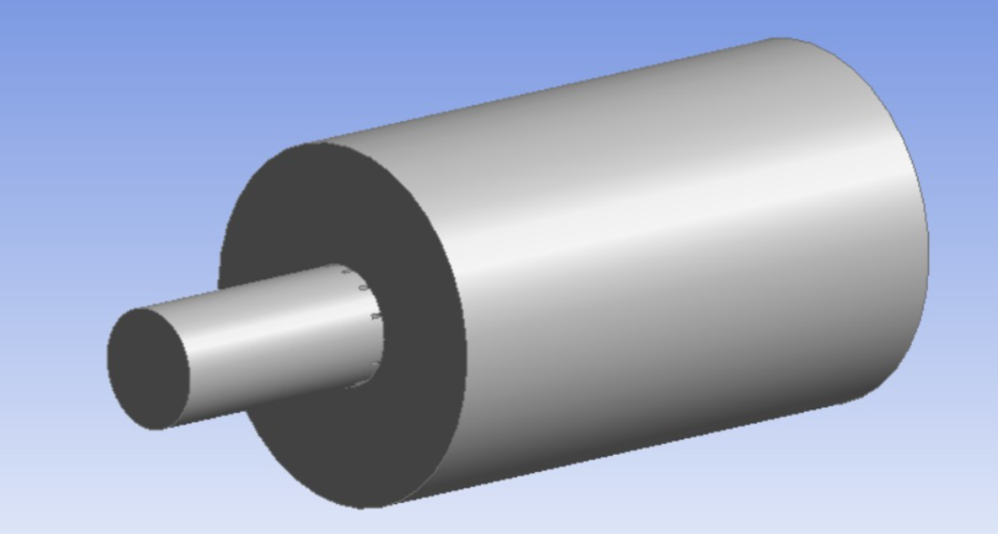
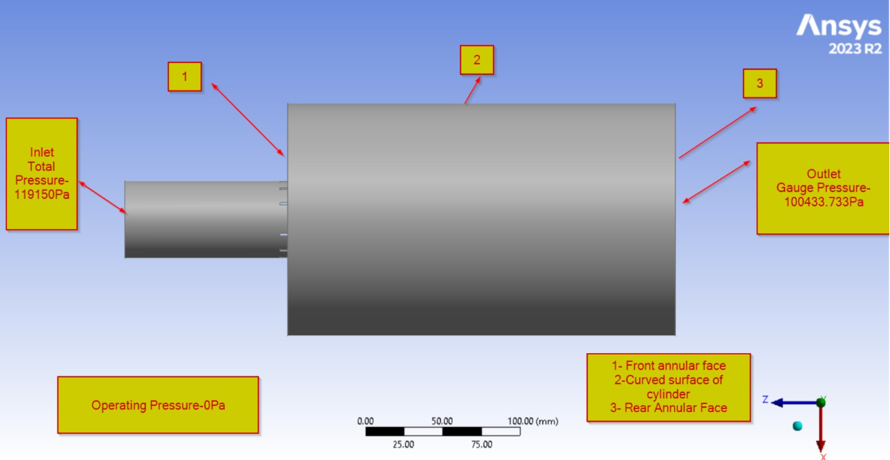
My main uncertainty is how to define the boundaries of this larger cylindrical domain. I have labelled them as 1 – front annular face, 2 – cylindrical curved surface, and 3 – rear face. I tried the following three approaches.
Case 1: I specified faces 1, 2 and 3 as pressure outlets at ambient pressure. During the calculation, Fluent reported reversed flow over portions of the pressure-outlet boundaries. I understand that this can represent ambient fluid entering the domain due to entrainment. However, the solution eventually became highly unstable and diverged, with very large mass imbalance and pressure/temperature limiting.
Case 2: I changed faces 1 and 2 to walls and kept only face 3 as a pressure outlet at ambient pressure. This case initially behaved much better and the solution appeared to converge for several hundred iterations. However, reversed flow eventually developed at the rear pressure outlet and increased significantly. My interpretation is that the jet naturally requires entrainment from the surrounding fluid, but faces 1 and 2 prevent any normal flow because they are walls. Therefore, the only open boundary available for the solver is the rear pressure outlet
Case 3: I then specified faces 1 and 2 as pressure inlets at ambient pressure and face 3 as a pressure outlet at ambient pressure. My intention was to allow ambient fluid to enter naturally through faces 1 and 2 while the main flow exits through face 3. However, this case was even more unstable. Fluent reported significant reversed flow at both the pressure-inlet and pressure-outlet boundaries, and the solution diverged.
I suspect that an important issue is that the outer cylindrical boundary is relatively close to the jet/screen region, so entrainment has a strong influence on these boundaries. I am therefore unsure whether changing only the boundary-condition type can solve the problem, or whether the ambient computational domain itself needs to be enlarged. Unfortunately, I am not sure whether I can change in my computational domain or not as of now. I have not used a pressure-far-field boundary because the surrounding experimental environment is still air, whereas the pressure-far-field condition requires a freestream Mach number.
Could you please advise what would be the physically appropriate boundary condition for faces 1 and 2 for this type of jet-into-quiescent-ambient problem? Should these boundaries permit entrainment or walls, and if so, which Fluent boundary condition would be most appropriate? Alternatively, should the cylindrical ambient domain first be extended farther away from the jet before applying an ambient-pressure boundary condition?
I have run these cases on my institute HPC system, and I can also attach the Fluent console messages/residual behaviour from all three cases if they would help diagnose the issue. Please answer taking into account of these attempts I have made. Thanks in advance.
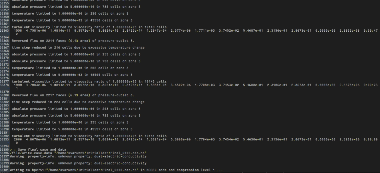
The above one is for first case.
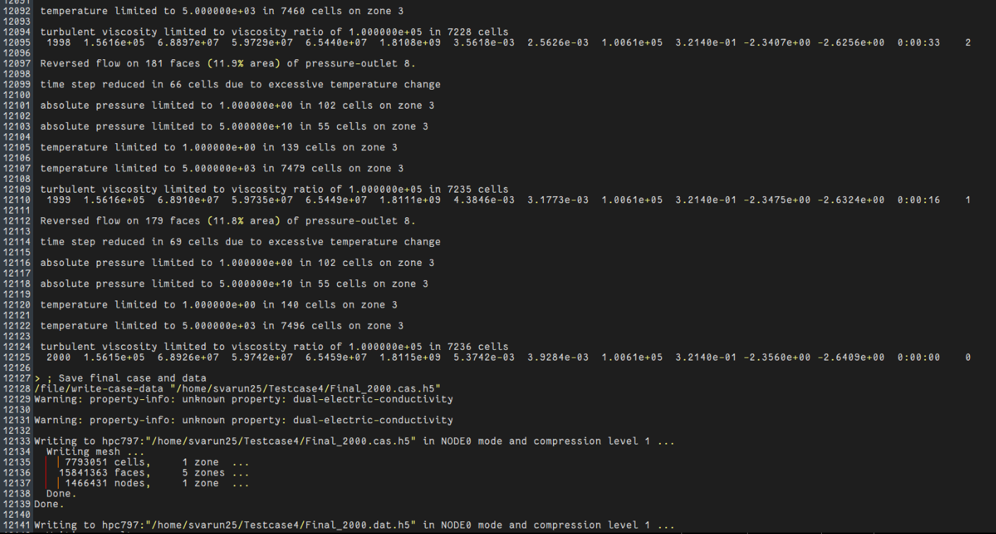
This is for 2nd case.
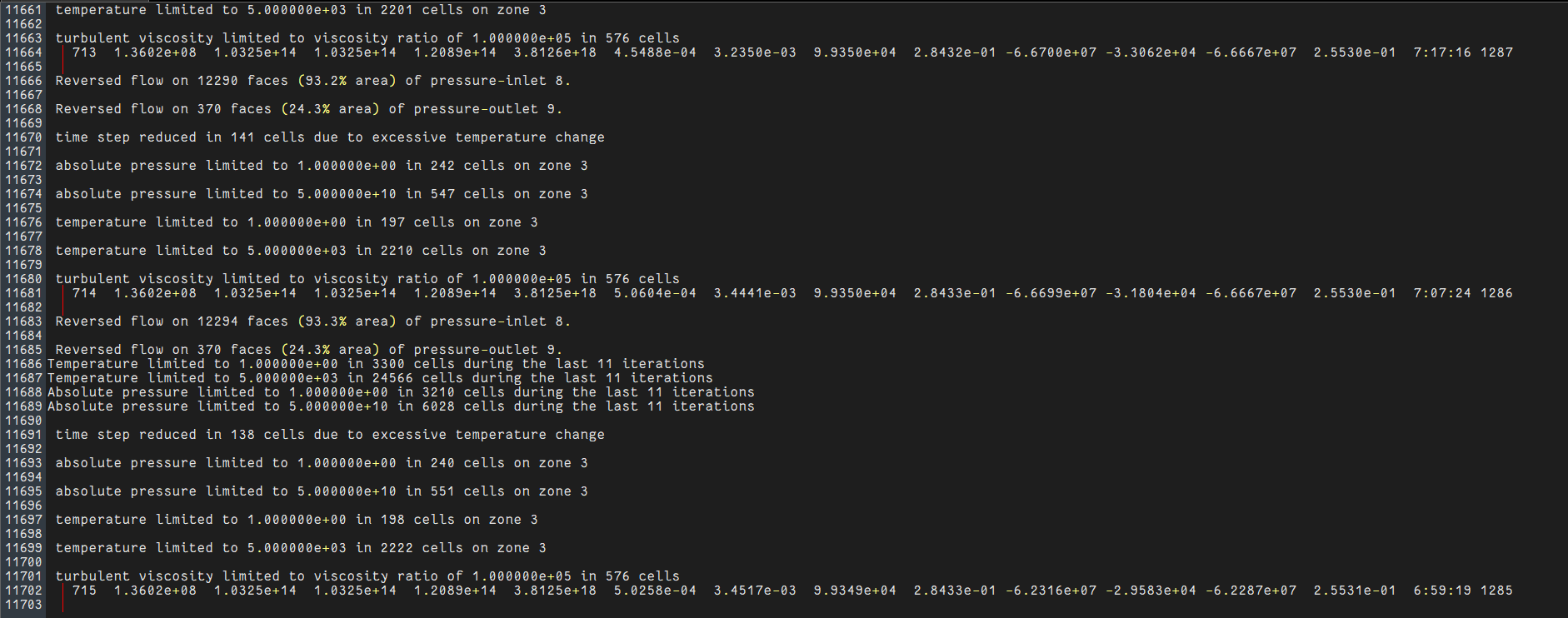
This is for 3rd case, residual value is even more higher. Highly unstable.
-
August 3, 2026 at 10:26 amSubscriber
What I thought was
I have to mention pressure in all outer faces of cylinder, so I used pressure outlet at all faces, but reverse flow was occuring at those faces. Flow demands like this. This is first case.In 2nd case, to prevent this, I used walls in all faces except rear face as pressure outlet. It was working fine upto some iterations then later reverse flow were occuring at those faces also. It is envitable.
So in 3rd case, I used pressure inlet in front and curved surface so that fluid comes in naturally instead of reversing but here reverse flow occurs in both pressure outlet and pressure inlet faces. I am confused what boundary condition to take for this free still ambient fluid.
-
August 3, 2026 at 12:10 pmSubscriber
I talked with my supervisor today, he told ideal condition is to take pressure outlet only since entrainment would be there. So case 1 is right. But dont know why solution is diverging and unstable. He told me to try case 2 first with more iterations and see whether it is converging or not? But do you have any other idea, please let me know. I will be happy to know and learn new things in this.
-
August 3, 2026 at 1:20 pm
Rob
Channel PartnerWhat have you done to investigate? What settings have you changed? Ie Courant Number/Time scale factor. How is the flow evolving?
For the boundary conditions. Pressure inlet/outlet or wall for 1 & 2 depending on what you're modelling. That's for you to decide based on what you plan on comparing data too. For the main inlet, I'd consider mass flow over pressure inlet, but also think carefully about initial conditions.
-
August 3, 2026 at 1:31 pmSubscriber
I have to validate experimental data, but before that I am observing what residual are behaving, how inlet mach no is converging, is there any mass balance between inlet and outlet. First I want to see whether solution is converging or not.
For 1 and 2, pressure outlet might be correct condition as told by my supervisor, but right now investigating whether flow is converging or not with taking them walls first.
I am doing steady RANS , density based solver, k-e model, refer solution methods and controls.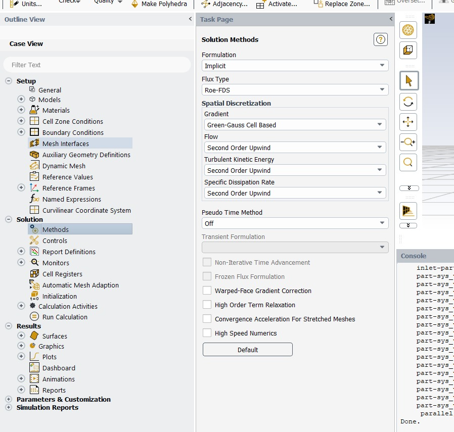
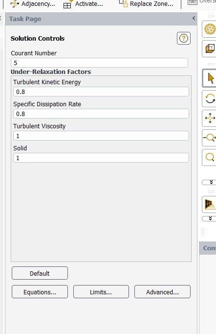
I dont know mass flow at inlet, I know only total static pressure and mach no at inlet. With isoentropic relation I calculated total pressure and used that. So inlet mach no should be converge to 0.35 and ambient static pressure is known.
Question: Do reverse flow at outlet or inlet affect convergence of solution, if no what might be the problem here?? Once setup beomes alright for this case, then I might try for case-1 i.e pressure outlet at all faces, where entrainment might occur all around the ambient. Do you have any other suggestion for outer cylinder faces other than pressure outlet?
-
-
August 3, 2026 at 2:07 pmChannel Partner
Why did you choose that solver?
Seriously, you have no idea what the mass flow is through the domain? Reverse flow may affect convergence and the end result, it depends how good the choice of back flow conditions are.
Re the boundary options. What does your experiment look like? What do you think you should use, and how do you plan on defending that choice in your report?
-
August 3, 2026 at 2:17 pmSubscriber
Since it is high speed or subsonic compressible flow at the inlet, density based solver is used. I am just following my senior work but he was having pipe in both ends but for me it is open fluid volume in downstream, that is the difference. Thats why I am using same solution methods and controls.
Yes, I dont have idea of mass flow through the domain. All I know is inlet mach no , inlet static pressure and ambient pressure.
Experiment was like- nozzle was there, outlet of nozzle is from where pipe starts, so all I know is static pressure of nozzle= static pressure of pipe inlet and it passes through screen and was expanding in ambient fluid. Thats all.
Regarding boundary conditions, I got to know from my supervisor today that it is better to use pressure outlet at all faces since all are exposed to ambient pressure which is same as case-1 discussed at the start. But before knowing this, I have runned my case again with taking walls first and seeing how residual and solution behaves. Now my ultimate question is why residual was not behaving properly or not converging when I ran it before with this condition??
If reverse flow is affecting convergence and end result then how to prevent this? But we were also discussing that this might represent entrainment, then it is inevitable right? I am struck with this, cannot able to move further from these ideas.
-
-
August 3, 2026 at 2:28 pmChannel Partner
And what does the training material cover regarding pressure in & out, and when to use pressure based over density based solvers? 0.3M isn't fast, nor will it be overly compressible.
If reverse flow is causing a problem what does the training suggest? Entrainment is inevitable as you're modelling a jet, reverse flow isn't inevitable but is a result of what you've modelled.
-
August 3, 2026 at 4:06 pmSubscriber
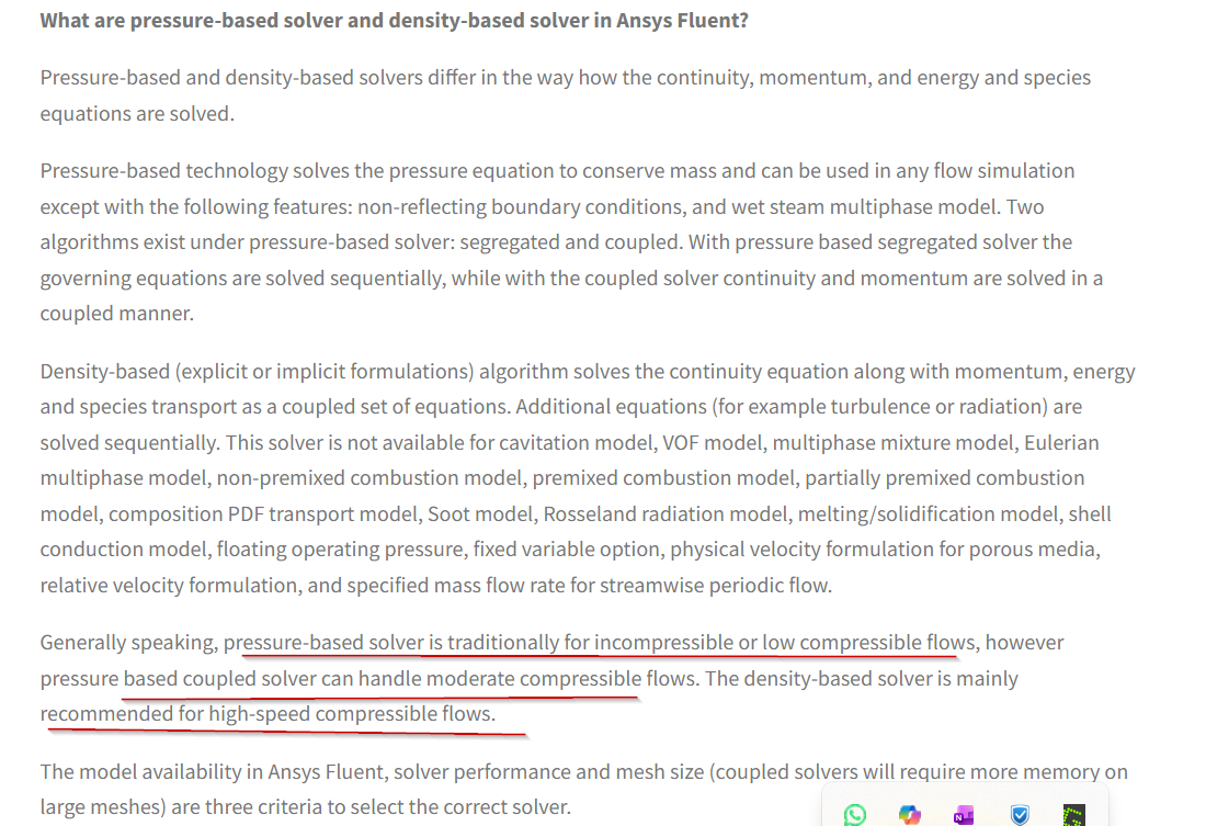
Yeah pressure based solvers can handle compressible flows. 0.35 isnt that much fast, but 0.35 is at inlet, but once it reaches screen , from continuity equation, fluid flow area decreased since there are wallls of distrotion screen, then velocity would be high there right? Then why cant we use density based solvers??
For a Pressure Inlet, you specify the total (stagnation) pressure and you do not need to know the velocity or mass flow beforehand. Fluent calculates the velocity and mass flow as part of the solution.
A pressure outlet in Fluent means you specify the static pressure at the boundary, it also permits reversed flow. The manual says backflow can occur even temporarily during iterations, so you should always provide realistic backflow values. Otherwise it will create convergence issues.
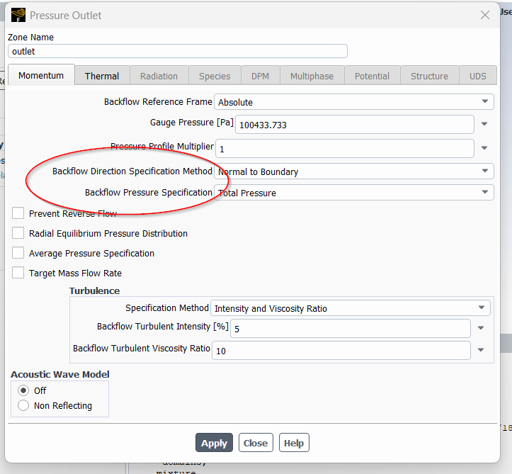
So two main things are backflow direction and backflow pressure- It basically tells us if there is fluid comes inside in outlet boundary- what pressure that incoming air has, and it comes at which direction?
Right now it has chosen total pressure, I think static pressure would be suitable here right? Also if direction of incoming fluid should be aligned with local flow of neighbouring cell, then I should change to "from neighbouring cell" from "normal to boundary". What do you think?
Do solution or residuals become better by incoperating these??
-
-
August 3, 2026 at 4:19 pmChannel Partner
You can use Density based solver, but as you're nowhere near the conditions it's necessary and given it's reputation for convergence I'd stick with PBCS. Even with compression/acceleration effects if you're sonic I'll be very surprised.
Correct, so Fluent must calculate the mass flow. But... As Fluent uses the inlet & outlet values, and when does it account for the flow restriction? How do initial conditions factor into convergence? You've got a load more reading to do.
Have a look in the manual to see what the static & total pressure options do. Both work, but static may be a better option here. Direction is also something to look at: both options are good, but here one may be better than the other.
-
August 3, 2026 at 4:30 pmSubscriber
Correct, so Fluent must calculate the mass flow. But… As Fluent uses the inlet & outlet values, and when does it account for the flow restriction? How do initial conditions factor into convergence? You’ve got a load more reading to do. What should I do now? I should read about what?
As it knows inlet and outlet values why it cant find the mass flow rate? What is obstructing that. Take example of simple pipe, which has one inlet and one outlet, here it will work right even though there is screen in between.
If initial condition is bad, and if we run for more iterations , then will it converge, or you are saying initial condition plays a important role in convergence irrespective of no of iterations we run??
Regarding direction you told one might be better than other, which one and why? For my case which one would be suitable??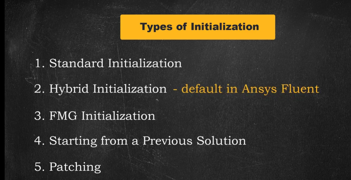
I have used hybrid initialisation, do I have to try FMG initilisation? Do you meant this or something else? Can you explain what things I have to do or read?One more thing I want to ask, I have ran the case with hybrid initialisation with more than 10000 iterations, I found that after 2500 iterations, reversed flow on no of faces started decreasing like from 2000, 1000,500,20,2,1 and the message dissappers, but still residual values are very high, I dont know or have any idea whether it will reduce or not.
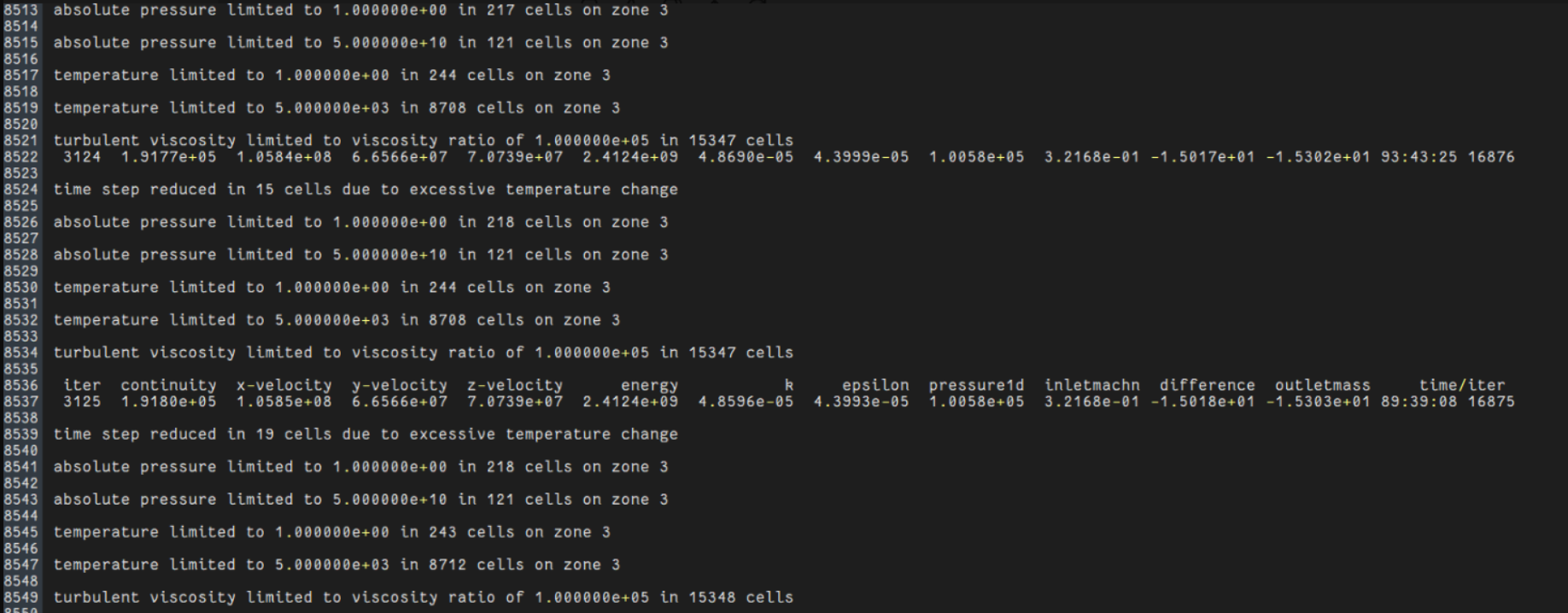
See residual values here. Do you think FMG initialisation will solver it better and give converged solution or any other solution??
-
August 4, 2026 at 9:15 am
NickFL
SubscriberAfter 10k iterations your initial condition is basically irrelevant. Think of it back to your numerical method class and when you had to do root finding with Newton-Raphson. Consider a function that had multiple roots, if you start with a good initial condition, you will approach the zero quickly. If you choose poorly, then you could be sent off to infinity. Hybrid initialization usually gives us a good start because it is solving a smoothed velocity field (see here for more information).
Look at the solution. See where it is not converging. Are there things in the flow field that should not be there? Just looking at residuals will NOT be enough.
-
-
August 4, 2026 at 9:15 amChannel Partner
The training covers what the initialisation functions do. Then consider how that impacts a system where pressure is known at both ends but there is no information about the middle. With a velocity boundary (and mass flow to a lesser extent) we fix a flow rate and pressure. If we know there is a flow restriction and likely a jet, which initial condition makes most sense? Would running with a velocity inlet & incompressible help? As mass flow is part of your solution, the initial condition can influence the route to convergence more so than when mass flow is part of the boundary settings.
Looking at the TUI, that's likely diverged. What does the flow look like? Residuals are only part of the solution.
-
August 4, 2026 at 10:11 amSubscriber
Dear Rob and Nick,
I have studied about initialisation some hours before. Yeah after 10k iterations initial conditions wont matter, it is right. But if your initial solution is very far away from actual solution, there will be large pressure corrections which leads to large velocity corrections, this can lead to unrealistic numerical values at the end, thats how it became unstable and diverging. This is my understanding, correct me if it is wrong. It should make sense somewhat. I heard FMG initilaisation works better for complex cases like this compared to hybrid.
I can show you total pressure and velocity counter for entire domain below,
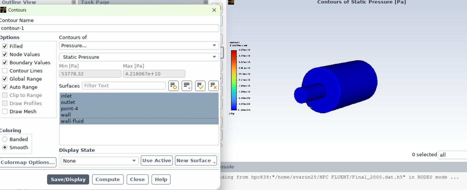
See here it is blue everywhere. I dont know why.
Same for velocity also,
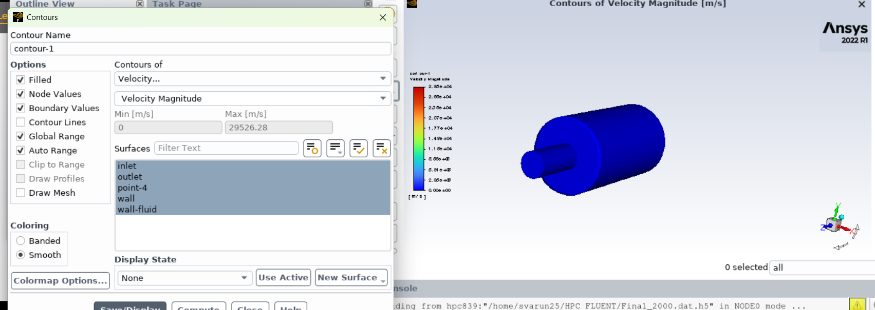
I know only pressure inlet and outlet, mass flow or velocity at inlet are not known.
I have no other idea other than using some other initialisation technique, I dont know whether it will work or not, I am seeking help regarding unstable residuals and solutions. Eagerly waiting for answer.
-
August 4, 2026 at 10:54 amChannel Partner
You're about right with the initialisation effect. FMG is usable, but standard and patch may also be of use here. Hybrid is generally best for most applications, but with pressure in & out plus a flow restriction and compressibility effects some care may be needed.
Why blue? Look at the scale more carefully. You also need to learn how to create planes etc for post processing inside the domain, they're covered in the tutorials.
-
August 4, 2026 at 11:15 amSubscriber
I dont know why it is blue throughout. I turned off global range , created xy plane at screen centre and plot is obtained. See below,
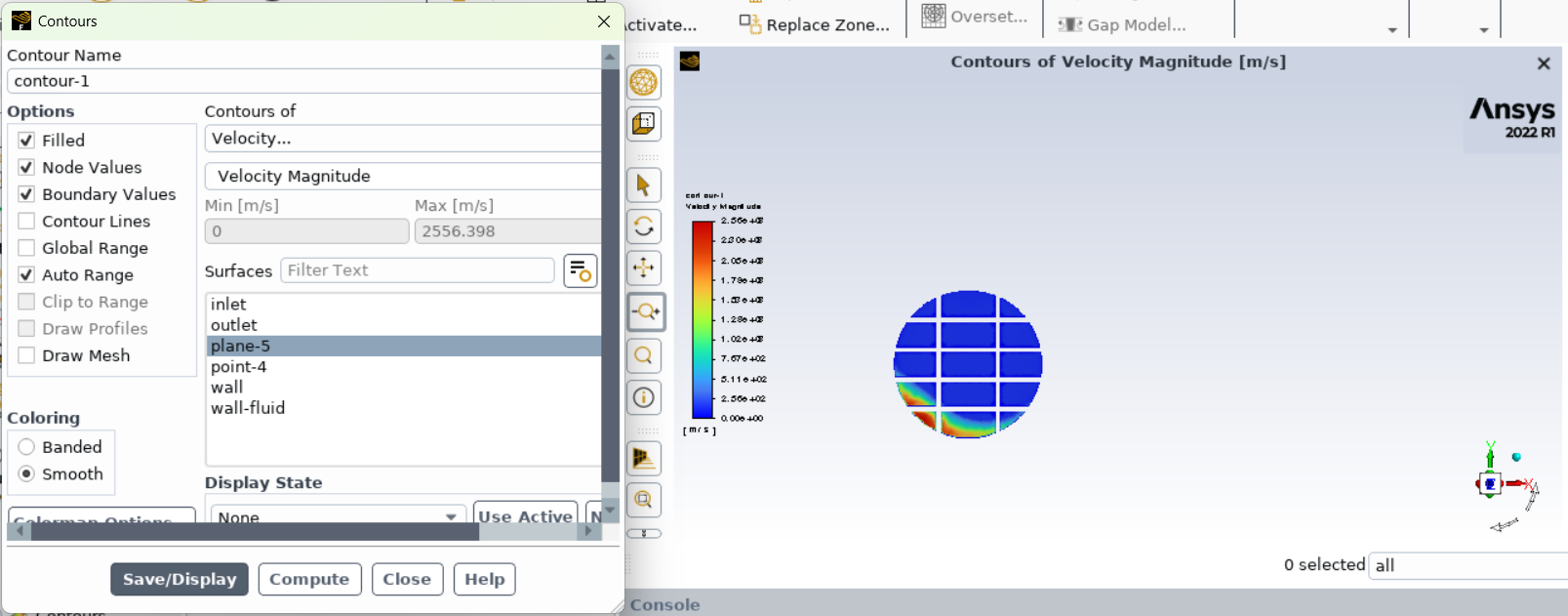
I dont know why it is blue in most of the regions , some red regions. This is at screen cross section
Next I created YZ plane as shown below,
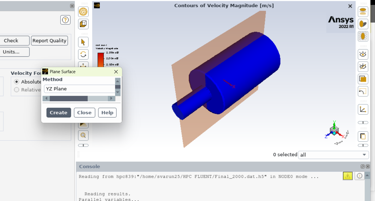
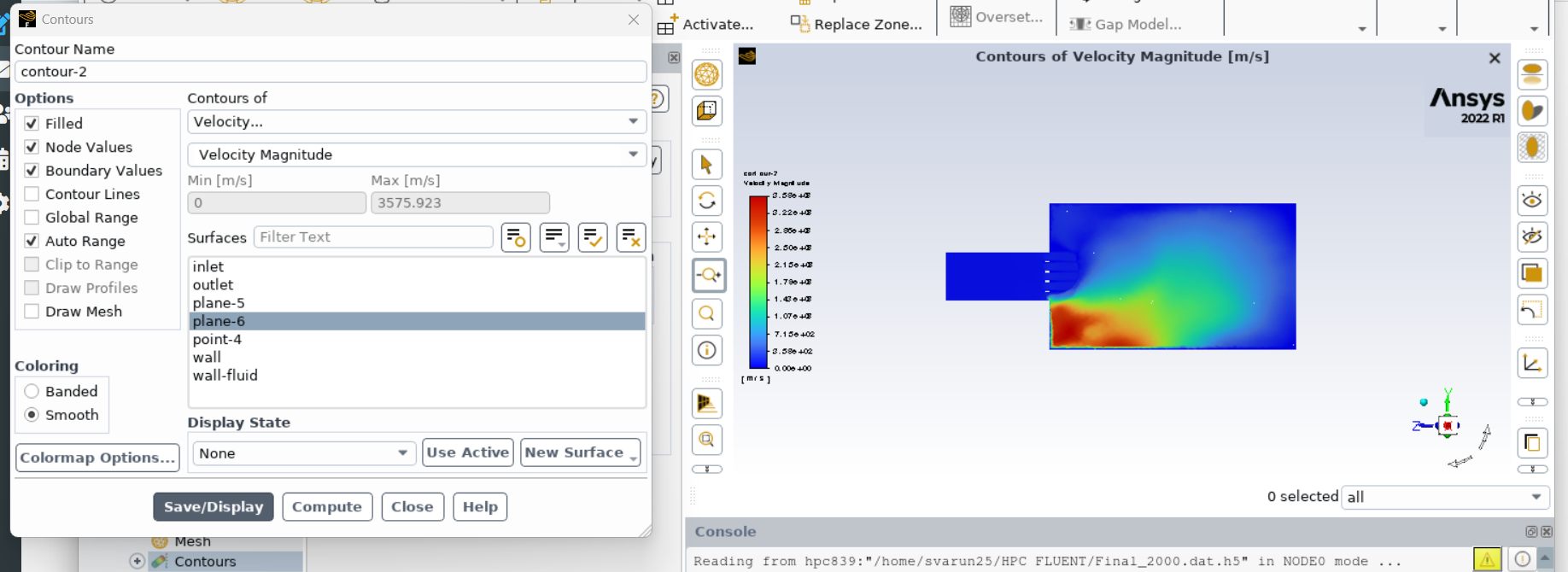
I hope image quality is fine.
Now what can we interpret from these? What has really gone wrong?
-
-
August 4, 2026 at 12:14 pmChannel Partner
And 2500m/s is reasonable for your simulation?
-
August 4, 2026 at 12:19 pmSubscriber
No.
There is something wrong, see in other places it is completely blue. I cant understand one thing, if residual are unstable and diverging then whats the use of seeing countour, it is obvious that it will give wrong values. Why there is a need to check these values?
What is the solution for this?
My senior has done this same geometry but it has pipe in downstream also. He used same total presssure at inlet and pressure at outlet, and he used hybrid initialzation and same solver settings. It has worked to him and solution has converged.
Here what is the problem, what is causing solution to diverge? Please explain elaborately.
-
-
August 4, 2026 at 2:02 pmChannel Partner
Because a failure to converge doesn't always mean a solution is nonsense. If you knew it was rubbish why did you just post residual values when asking questions, as opposed to changing suitable settings and trying again?
So, what's different between your model and their model? Think through both geometry and likely flow field for both their and you cases.
-
August 4, 2026 at 2:10 pmSubscriber
I dont know what suitable settings to change. Only difference is computational domain, it will look like pipe throughout with screen, mine is expanding in open ambient volume.
I asked questions posting residual values because I cant able to figure it out why it is diverging or unstable, that snapshot might help you to identify what might be the issue, thats the reason.
For his case also, there will be jet-wake interaction in downstream, there will be mixing and this mixing weakens as you go downstream.
For my case it will look like open shear flow after the screen, my case is also studying that jet wake interaction in downstream. I know all these, but I cant able to understand why solution is diverging or unstable. Note solver settings are kept same only. Can you able to comprehend what might be wrong?
-
-
August 4, 2026 at 2:28 pmChannel Partner
Have you tried PBCS? What about mass flow inlet at roughly the value you expect to help Fluent get a better initial condition? What about incompressible flow to see what's going on?
Posting residual values just tells me that Fluent's not happy, the fact you're hitting limiters is another clue. Diagnosing divergence isn't just a case of looking at a couple of numbers and magically determining the cause. It's a careful review of the whole model, and then trying without some of the additional models/settings to see what happens.
-
August 4, 2026 at 2:43 pmSubscriber
With this density based solver , I am getting mass flow at inlet around 0.28kg/s(in last iterations, there is difference of values only in 4th or 5th decimal place). I havent tried PBCS.
Under PBCS, anything to change from below:
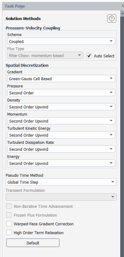
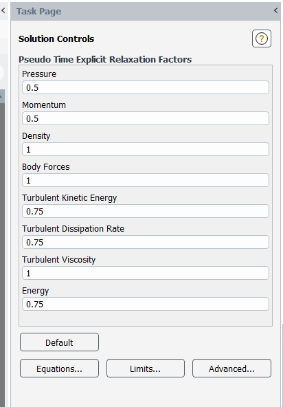
Is it fine to go with total pressure at inlet and static pressure at outlet under PBCS??
My supervisor told to try with density based solver only, how can I convice him that pressure based solver also works, this also makes density and viscosity constant. Ideal gas and sutherlad law wont be applied here. As I told before, flow will accelerate due to reduction in flow area, then do PBCS works good here??
-
August 4, 2026 at 4:25 pmChannel Partner
I'd drop turbulence to first order and switch on HOTR, but also review two equation models and jetting effects. Don't forget time factor.
PBCS doesn't make density & viscosity constant, they can vary in pretty much any of the solver options. But I'd probably not bother varying anything other than density, even that's of marginal concern until you have some idea of the flow field. Similarly pressure in & out, yes you can have those options but until something is working I'd keep to a very simple set up.
-
August 4, 2026 at 4:49 pmSubscriber
I have tried with settings shown above i.e second order. I will share observations tomorrow, let it run for tonight.
-
-
August 5, 2026 at 1:58 amSubscriber
Dear Rob,
I tried with PBCS, the results are insane. It has run upto 1300 iterations, see the residuals below.
I have taken density as ideal gas and sutherland viscosity law. Same boundary condition and values.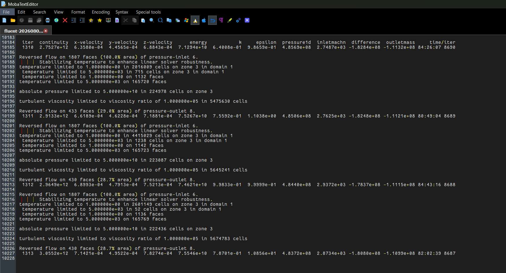
The residuals are going above 10^12, which is not a good sign. See inlet mach no value with iterations,
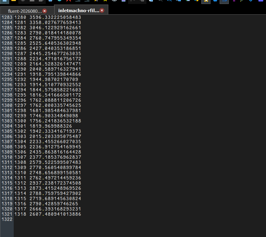
It is very high and unrealistic value. With density based solver, residuals are high but it never gave unrealistic value for mach no and mass difference between inlet and outlet. See mass difference value with iterations below,
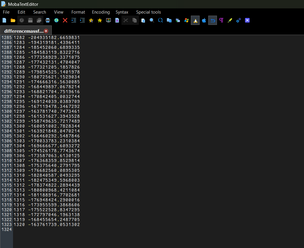
What should I do now??
-
August 5, 2026 at 7:07 amSubscriber
- Do something simple just to validate that everything before is working. Solve it with 1 [m/s] velocity-inlet and an atmopheric pressure outlet (0 relative pressure). Use incompressible air. Keep it simple! Does this work?
- You need to take some time to think about what is going on between questions. In order to investigate what is going on you need to review the flow field in detail. What does your initial condition look like? What region in the solution domain is causing the problem? Is there something "broken" there? I assume you have taken courses in mathematics, fluid dynamics, numerical methods, etc. Now is the time to apply that knowledge to real world problems. It is typical to take time debug a model as there are thousands of things that could be causing problems. Expecting it to be perfect on the first try is unrealistic.
- When the residual ist E+12, you can stop it well before this point. Once you get results with residuals like this it is generally too late to identify where the problem is. Go back to my example with Newton's method. When your "root" that you are trying to get is 100 and your solution iteration is going from +2e10 to -2e10, you have a problem. What do you do? You go back to your initial guess and you watch how it changes after 1 iteration. Then 10. Then 20. Then you can start to see where the problem is. You can do the same sort of thing here. 1000 iterations when your solution already failed at 50, there is no value in that.
-
August 5, 2026 at 8:52 amSubscriber
Dear Nick and Rob,
As you said, I tried with velocity inlet of 1m/s, outlet at ambient pressure, SIMPLE scheme with all second order, change all properties of fluid to constant.
I initially ran for 200 iterations, it was going good for 100 iterations, then later same type of warnings started to come like "temperature limited to..." and by the end of 200 iterations, residuals are increasing from where it was started.
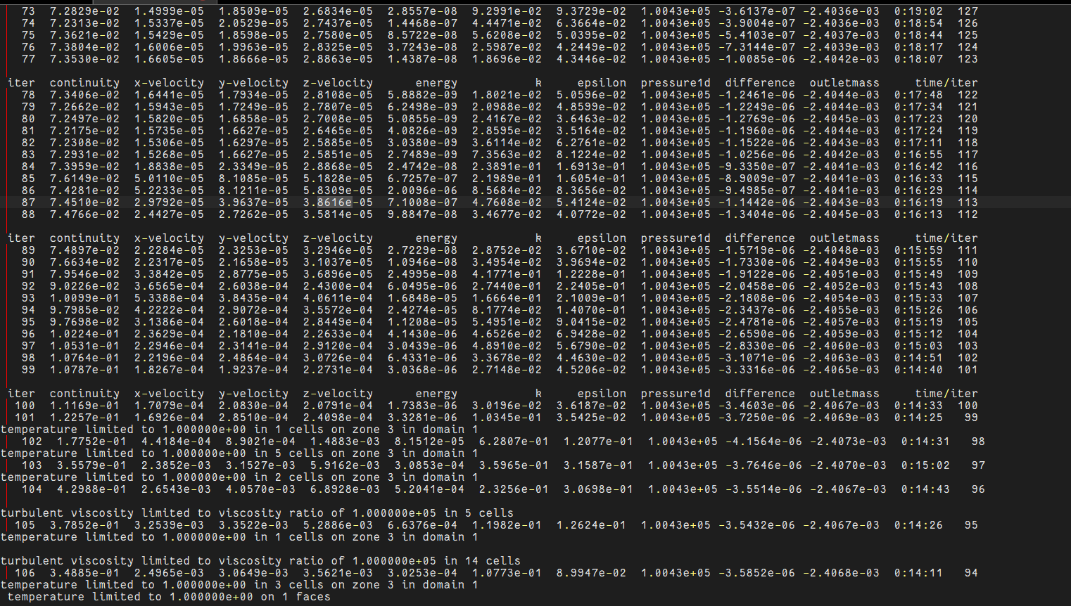
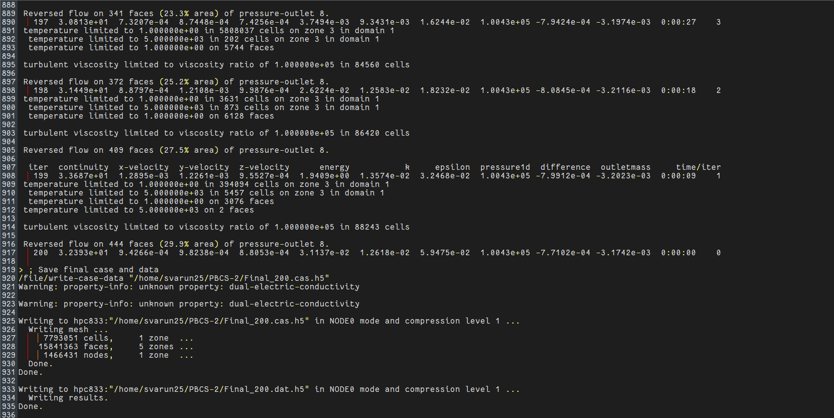
I dont know why these messages are coming- it may be due to some unrealistic values occuring during pressure and velocity corrections ig. Your views??
-
August 5, 2026 at 9:01 amSubscriber
Keep it as simple as possible. Why are you solving Energy? If it is incompressible and for a simple model do not include heat on walls. You want to start with the simplest model possible and then slowly add the physics on to it.
Again residuals tells us nothing other than it diverged. Why did it, we cannot tell from this. Think of it like a murder. The residuals tell us the model died, but we need to do an autopsy to understand how it died. The autopsy requires looking at the flow field and identifying potential sources of divergence.
-
August 5, 2026 at 10:06 amSubscriber
So, should I check velocity counter by cutting plane at various iterations?
-
August 5, 2026 at 10:48 amChannel Partner
Yes. But do this before it diverges. What is seen in the flow field at about iteration 80?
Also think about what's happening before posting: why do you think it's happening?
-
August 5, 2026 at 2:15 pmSubscriber
I have tried 100,125,150 iterations.
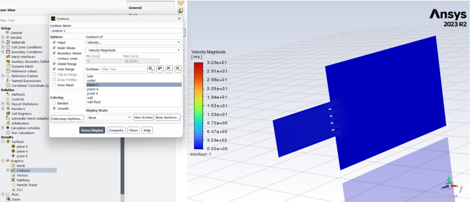
This is the counter I am getting for all three. No change. It is zero everywhere.
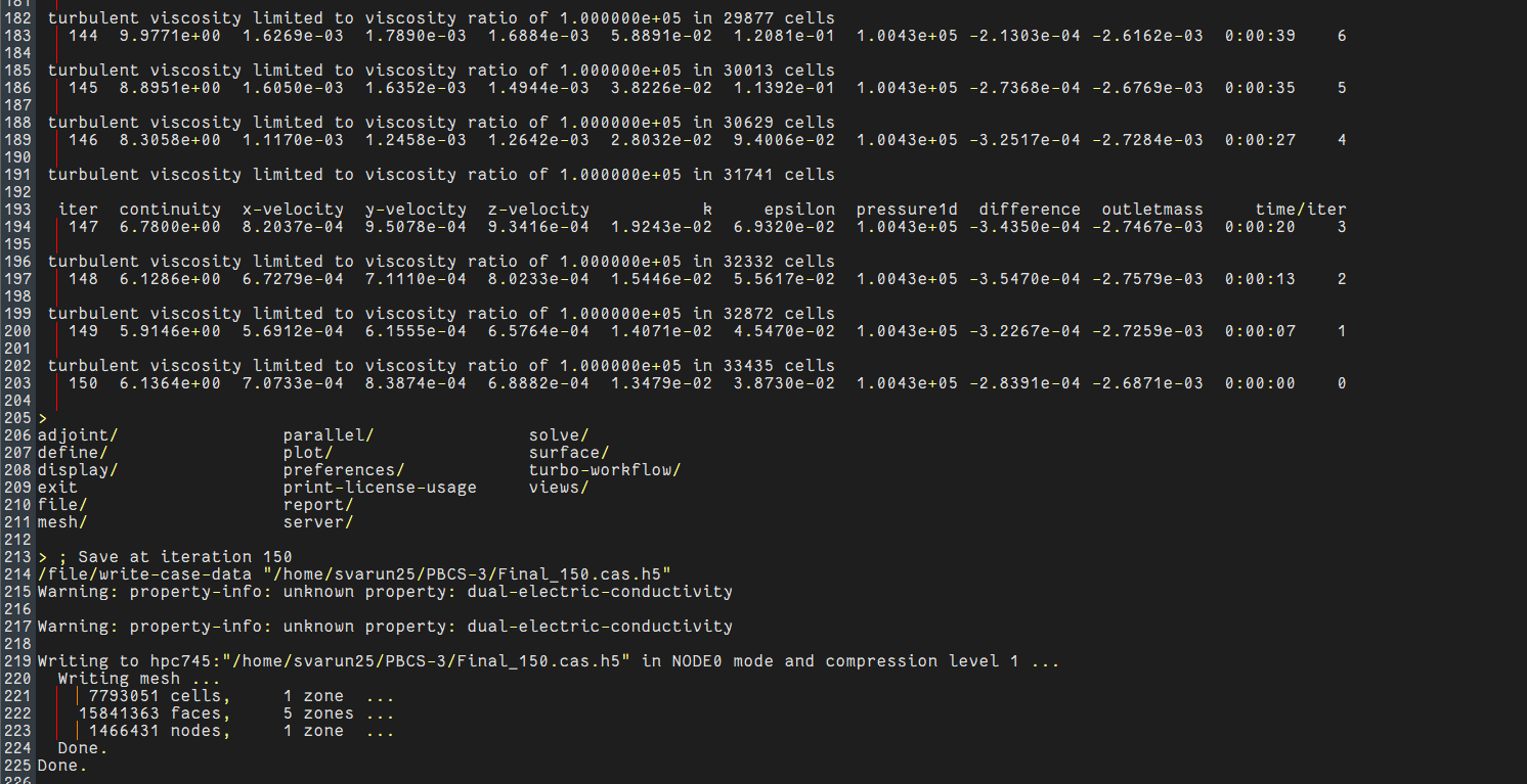
Residual are further expected to increase. What can be done?
-
-
August 5, 2026 at 2:47 pmChannel Partner
With an inlet velocity of?
-
August 5, 2026 at 2:57 pmSubscriber
I used 1m/s as suggested by Nick.
-
-
August 5, 2026 at 3:09 pmChannel Partner
So what velocity range would you expect in your domain? Compare that to the plot you posted.
-
August 5, 2026 at 3:11 pmSubscriber
Inlet mach no is 0.35. We can find velocity using mach no formula, but you were telling to try 1m/s first and check how solutions are behaving. Should I enter actual velocity at inlet. Ma=v/root(gamma*R*T), should I find v here and substitute there??
Why 1m/s is not working here??
-
August 5, 2026 at 3:21 pmChannel Partner
So, with 1m/s on the inlet roughly what velocity range would you expect to find in a model? Then look at the scale on your image.
-
August 5, 2026 at 5:05 pmSubscriber
From the image, velocity scales from 0 to 32m/s(max). But in reality, it wont accelerate to this much speed. This is my understanding. I cant calculate how much velocity range we can expect, but maximum velocity will be in screen cross seection since there is reduction in fluid area, but it wont be 32 times higher than initial velocity(1m/s). From this what we can interpret??
-
August 6, 2026 at 7:30 amSubscriber
Do a hand calcuation of what you expect the velocity to be if you have an inlet region of 1 [m/s]. You always have to do a hand calcation before the simulation so you know what the answer "should" be.
On that cut plane that you have, it is all blue so the "high speed" region is not on this midplane. Where is it? Is it near a boundary? If so, what are your boundary conditions on those boundaries? What is the mesh qualility in this region? Follow the clues to help you debug the model.
-
August 6, 2026 at 9:16 amChannel Partner
And maybe then look at the display options for Range on the contour panel.
-
August 6, 2026 at 10:33 amSubscriber
For rough calculation, from continuity, the screen has porisity of 0.7. So velocity must be 1.43 to 2m/s from acceleration. When it expands, it decreases further and contact in ambient fluid.
You are right, maximum velocity is not in that plane, I tried using cell registers to find maximum velocity and found in which cell it corresponds to that velocity. I will send snaps, please look into that and tell me whether it is right or wrong.
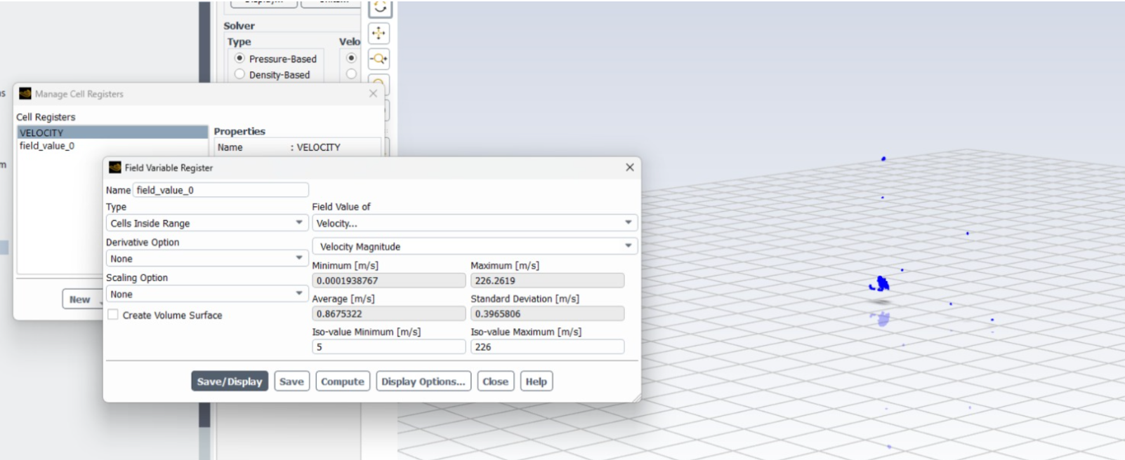
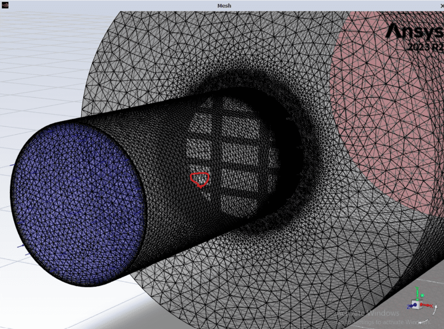
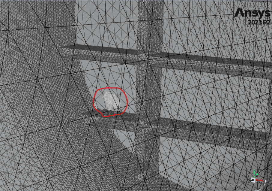
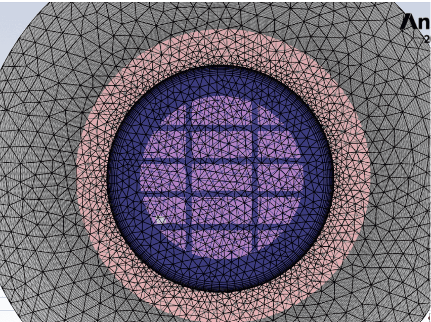
I hope you can find location of those cells which contribute to higher velocities. This is my observation.
-
-
-
August 6, 2026 at 10:38 amSubscriber
Dear Rob and Nick,
I have done one more thing,
I reduced under relaxation factor from 0.7 to 0.4 for momentum and 0.2 from 0.3 for pressure. I changed first order upwind for turbulence, and used same 1m/s velocity at inlet. It was good upto 500 iterations and later, residual are gradually increasing. See below pic at end of 841 iterations,
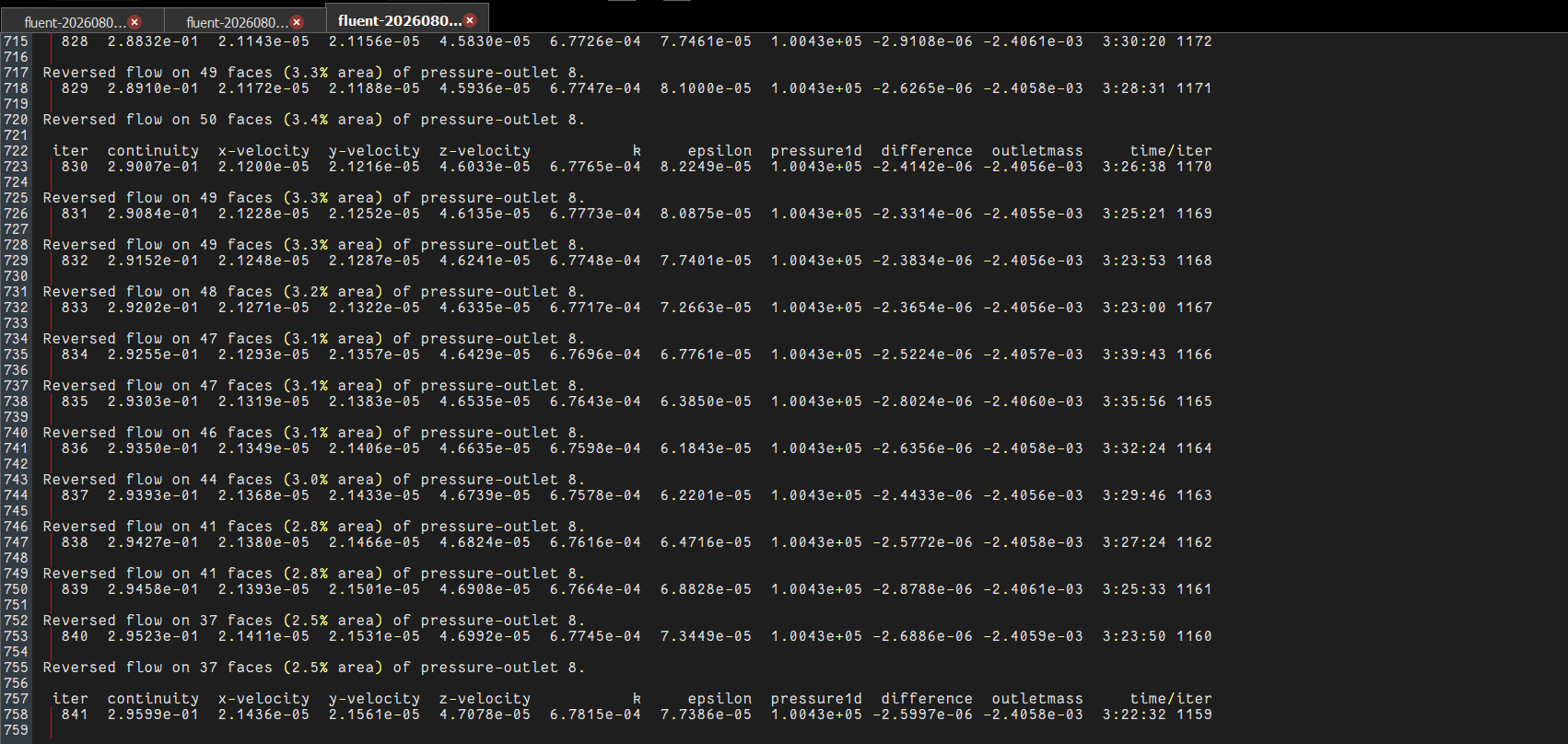
Residual are increasing gradually not suddenly, I dont know whether it will converge or not. But even though residual are set at 10e-6, when I check values of inlet and outlet mass flow, difference between them is roughly 0.1%.
Please suggest me what I have to do now? I have sent my observation in above post also.
-
August 6, 2026 at 11:44 amSubscriber
See for current case, I am doing, when I switch off global range, I got correct plot
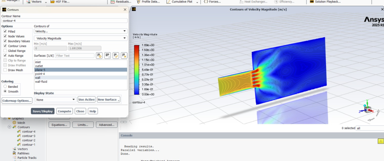
Result is much better now.
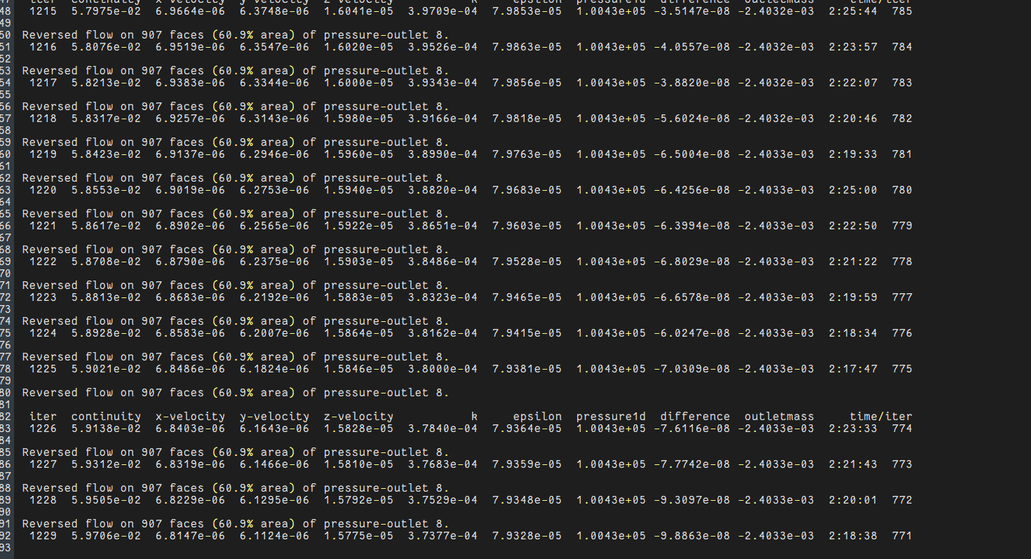
Residual also decreasing now(I meant before it was having 7.3e-2 , now it has come to 5.9e-2). But it is increasing for sometime and decreasing for some other time. I hope I continue with this, tell your opinion.
-
August 6, 2026 at 12:25 pmChannel Partner
How does what you're seeing compare to the tutorials that you've done?
-
August 6, 2026 at 12:45 pmSubscriber
I havent done simulation for similar kind of geometry, but if you see the plot, range is from 0 to 1.69m/s which is quite reasonable. Let me see whether it is converging or not, and how many iterations it is taking?
But main change is I have taken simple velocity inlet of 1m/s, constant fluid properties, energy is off, first order turbulence upwind , reduced URF and simulated it.
If you have anything to suggest, you can go ahead, let me see how this simulation is going towards when iteration is increased.
-
-
August 7, 2026 at 2:00 amSubscriber
Hi rob and nick,
This also unfortunately after 2000 iterations, contiuity residual have increased to 10e+5 and velocity residual remain under 10e-5. I used a velocity inlet of 1m/s and pressure outlet for simple testing
Residual was unstable after some iterations
Then I reduced URF for momentum to 0.4 and for pressure 0.2. I used SIMPLE scheme with first order turbulent schemes
Initially upto 2000 iterations it was doing good. Residual was like 10e-3 for continuity and 10e-6 for velocity
But later after 2000 iterations at the end of around 4500 iterations continuity was 10e+5 and velocity remains small i.e 10e-5
Why continuity residual increased? How to solve this issue?? See below imageReversed flow on 432 faces (28.3% area) of pressure-outlet 8.
4995 9.3236e+05 7.3246e-05 7.6516e-05 1.5449e-04 2.6899e-03 1.1426e-02 2.5340e+00 2.5364e+00 5.2376e+10 7:41:16 2005turbulent viscosity limited to viscosity ratio of 1.000000e+05 in 5435577 cells
Reversed flow on 430 faces (28.1% area) of pressure-outlet 8.
4996 9.3207e+05 7.3275e-05 7.6607e-05 1.5458e-04 2.6949e-03 1.1423e-02 2.3811e+00 2.3835e+00 5.2657e+10 7:43:04 2004turbulent viscosity limited to viscosity ratio of 1.000000e+05 in 5438808 cells
Reversed flow on 431 faces (28.2% area) of pressure-outlet 8.
4997 9.3499e+05 7.3363e-05 7.6689e-05 1.5465e-04 2.6939e-03 1.1422e-02 2.4226e+00 2.4250e+00 5.2954e+10 7:51:16 2003turbulent viscosity limited to viscosity ratio of 1.000000e+05 in 5441909 cells
Reversed flow on 432 faces (28.3% area) of pressure-outlet 8.
4998 9.3605e+05 7.3512e-05 7.6721e-05 1.5473e-04 2.6935e-03 1.1420e-02 2.3463e+00 2.3487e+00 5.3217e+10 7:52:00 2002turbulent viscosity limited to viscosity ratio of 1.000000e+05 in 5445168 cells
Reversed flow on 433 faces (28.4% area) of pressure-outlet 8.
4999 9.4045e+05 7.3684e-05 7.6749e-05 1.5481e-04 2.6968e-03 1.1422e-02 2.6665e+00 2.6689e+00 5.3453e+10 7:35:39 2001turbulent viscosity limited to viscosity ratio of 1.000000e+05 in 5448260 cells
Reversed flow on 432 faces (28.3% area) of pressure-outlet 8.
5000 9.4696e+05 7.3873e-05 7.6814e-05 1.5484e-04 2.7086e-03 1.1418e-02 2.7018e+00 2.7042e+00 5.3783e+10 7:39:10 2000turbulent viscosity limited to viscosity ratio of 1.000000e+05 in 5451116 cells
Reversed flow on 435 faces (28.5% area) of pressure-outlet 8.
5001 9.5099e+05 7.4053e-05 7.6789e-05 1.5482e-04 2.7163e-03 1.1416e-02 2.8184e+00 2.8209e+00 5.4161e+10 7:56:26 1999turbulent viscosity limited to viscosity ratio of 1.000000e+05 in 5453903 cells
Reversed flow on 435 faces (28.6% area) of pressure-outlet 8.
5002 9.5641e+05 7.4285e-05 7.6727e-05 1.5481e-04 2.7173e-03 1.1416e-02 3.1583e+00 3.1607e+00 5.4552e+10 7:55:54 1998turbulent viscosity limited to viscosity ratio of 1.000000e+05 in 5456839 cells
Reversed flow on 436 faces (28.6% area) of pressure-outlet 8.
iter continuity x-velocity y-velocity z-velocity k epsilon outletmass difference pressure1d time/iter
5003 9.6215e+05 7.4414e-05 7.6631e-05 1.5480e-04 2.7206e-03 1.1410e-02 3.1566e+00 3.1590e+00 5.4896e+10 7:52:51 1997turbulent viscosity limited to viscosity ratio of 1.000000e+05 in 5460443 cells
Reversed flow on 436 faces (28.7% area) of pressure-outlet 8.
5004 9.6448e+05 7.4569e-05 7.6563e-05 1.5482e-04 2.7182e-03 1.1411e-02 3.5054e+00 3.5078e+00 5.5233e+10 7:51:51 1996turbulent viscosity limited to viscosity ratio of 1.000000e+05 in 5464787 cells
Reversed flow on 436 faces (28.6% area) of pressure-outlet 8.
5005 9.6836e+05 7.4644e-05 7.6496e-05 1.5486e-04 2.7076e-03 1.1408e-02 3.7489e+00 3.7513e+00 5.5531e+10 7:55:49 1995turbulent viscosity limited to viscosity ratio of 1.000000e+05 in 5468175 cells
Reversed flow on 434 faces (28.5% area) of pressure-outlet 8.
5006 9.6820e+05 7.4738e-05 7.6470e-05 1.5488e-04 2.7135e-03 1.1401e-02 3.2221e+00 3.2245e+00 5.6147e+10 7:54:44 1994turbulent viscosity limited to viscosity ratio of 1.000000e+05 in 5471695 cells
Reversed flow on 433 faces (28.5% area) of pressure-outlet 8.
-
August 7, 2026 at 8:38 amChannel Partner
Compare the flow at 1900 iterations with later on. How are the monitors changing?
Posting residuals just means more electrons are inconvenienced as it's overly useful: they just tell us it's not working.
-
August 7, 2026 at 10:04 amSubscriber
I found one more thing,
I found some cells from outer cylinder which has velocity more than 5m/s and some cells in screen faces. I cant able to post images in newly migrated ansys learning forum website. It is showing "uploading pasted image" , but it is struck and not getting pasted. I want to show that.
Once i found those cells, what to do next? There is no sizing control done for outer cylinder, it uses global element size 5mm. What to do for screen if already face sizing is applied?
What about converting tetra mesh to polyhedral mesh, where it improves quality and reduce cell count as well? -
August 7, 2026 at 10:37 amChannel Partner
There look to be a few teething problems with the new system - it's being looked into.
You can convert to poly, but that's why Fluent Meshing was mentioned several times during the previous thread: I don't know if converting will do much for your flow issue. As I don't know why you're seeing the odd acceleration you're going to need to do some more investigation. Changing UR factors rarely does much in the newer solvers, and typically only delays problems. This is also why you were advised to get a rough tet mesh running over a month ago.
-
- You must be logged in to reply to this topic.



-
peteroznewman
 6880
6880 -
scabo
 1906
1906 -
Dennis Chen
 1544
1544 -
javat33489
 1344
1344 -
NickFL
1217



© 2026 Copyright ANSYS, Inc. All rights reserved.

 You are navigating away from the AIS Discovery experience