-
-
November 19, 2024 at 12:53 pm
mloeland
Subscriberhello
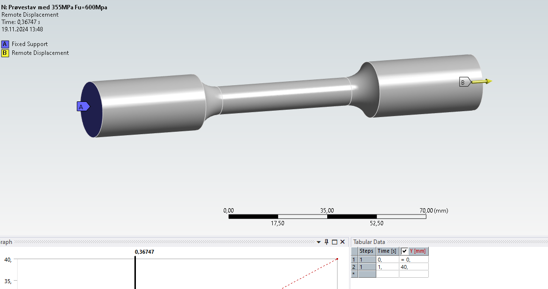
iam using differnt materials on a tensile test to check different things.
I came across something i cant figure out, someone please help me explain...
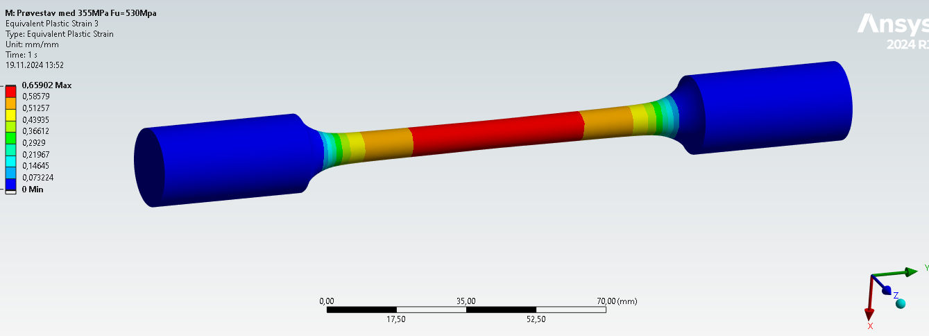
i have a tensile test, the section in the middle is 50mm long. i apply a displacement of 40mm in one end and its fixed in another...By the strain formula, this ε= ΔL/L, this should give a strain of 80% in my analysis...
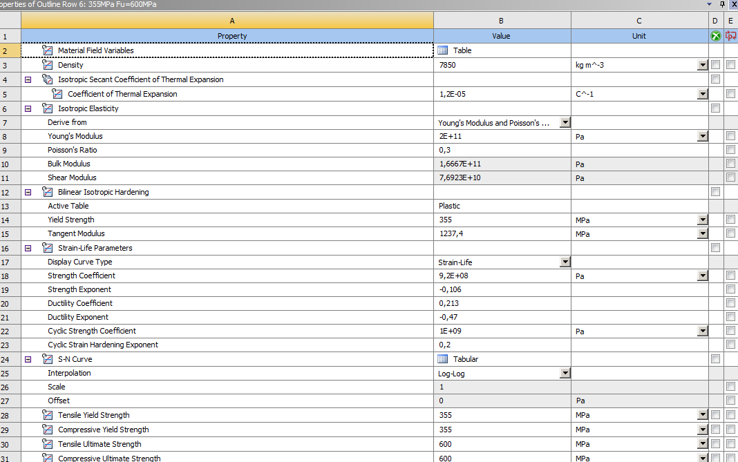
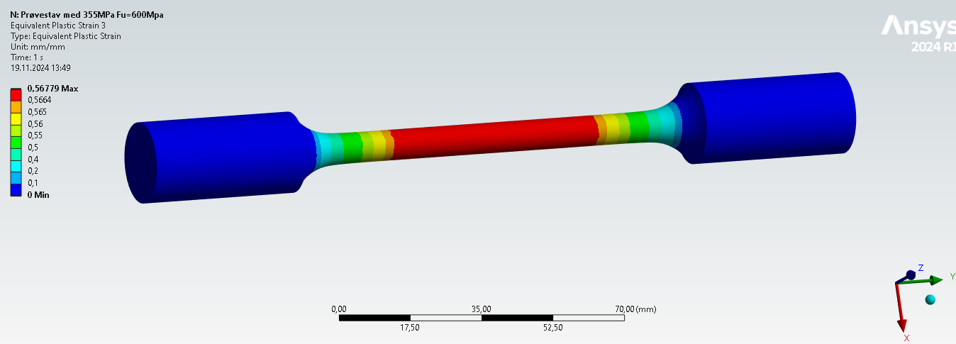
But in my analysis the strain varies from 56%-67%, depending on which material properties i use. Can someone explain why it is like this?
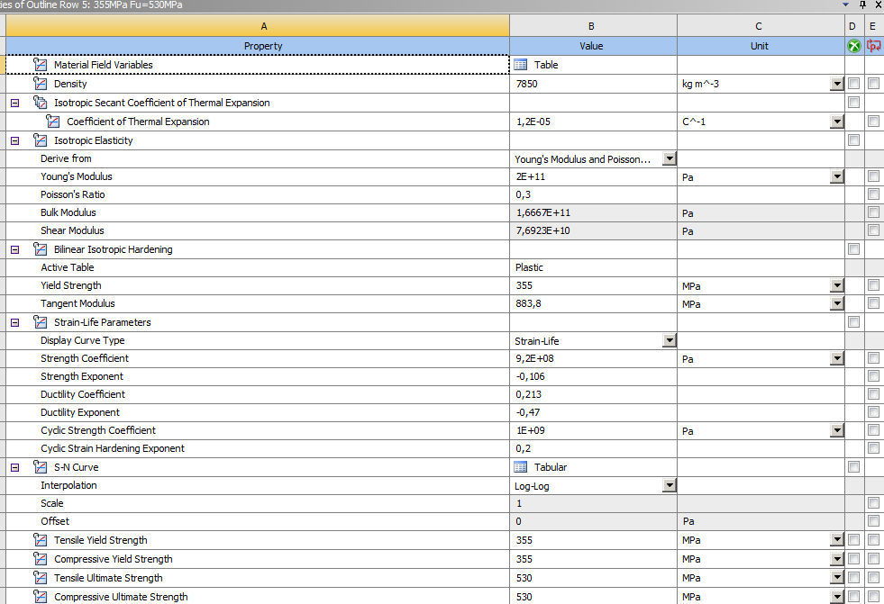
Same boundary conditions as above, but different material:
-
November 19, 2024 at 4:02 pm
Dennis Chen
SubscriberMaybe try turning off large deflection if it's on and suppressing bilinear isotroopic hardening and run this again to see what you get.
-
November 19, 2024 at 4:14 pm
Armin
Ansys EmployeeHello,
Please consider the following points:
Note that the values displayed are TRUE strains so you need to convert your engineering strain to true strain. You can also check the strain along the loading direction (major principal strain) rather than equivalent strain as the stress state deviates from uniaxial tension after some point (due to localization).
As you employ different plasticity parameters in your model, the tensile specimen localizes differently (as evident by the contour plots in your screenshots) and the strain is no longer uniform at lager strains. That explains the differences in strain magnitudes in the two cases you evaluated.
-
November 20, 2024 at 8:22 am
mloeland
Subscriber- You can also check the strain along the loading direction (major principal strain)
- How do i check this? i cant see an expression for it, could you help me?
-
November 20, 2024 at 5:55 pm
- You can also check the strain along the loading direction (major principal strain)
-
- You must be logged in to reply to this topic.


-
4763
-
1565
-
1386
-
1242
-
1021

© 2026 Copyright ANSYS, Inc. All rights reserved.

