We have an exciting announcement about badges coming in May 2025. Until then, we will temporarily stop issuing new badges for course completions and certifications. However, all completions will be recorded and fulfilled after May 2025.
Fluids

Fluids

Topics related to Fluent, CFX, Turbogrid and more.

Dynamic Mesh Problem for Axial and Rotational Movement of a Propeller

    • peteroznewman
      Subscriber

      A cylindrical tank is completely filled with paint. In the tank are two propellers on a vertical axis that spin and move vertically together to mix the paint. In the complete model, there are two phases that have separated into more and less dense fluids. The purpose of the model is to evaluate the mixing of those two phases.

      A simpler version of the problem with only rotational propeller movement is working using the Sliding Mesh method. In the image below, some artifacts at the interface between the rotating zone around the propeller and the static zone of the tank can be seen. This was a coarse mesh to establish that the mesh motion was working. Any suggestions about that artifact are welcome but that could be addressed separately in a different discussion.

      The topic for this discussion is to add the axial motion of the propellers to the model.

      The first idea to achieve that is to split the tank into three zones: top, middle and bottom. This was done in SpaceClaim and Shared Topology was used to mesh through the interior faces at the split planes to avoid adding interfaces. The rotating propeller zones are enclosed in the middle-static tank zone. The sliding mesh method used for the propeller zones had the “Relative To Cell” setting changed from Absolute to Relative to Cell Zone so the propeller zones would translate with the middle zone.

      Dynamic Mesh was selected to deform the top and bottom static zones of the tank using Layering only for the first attempt.

      Mesh Motion has been defined on the middle-static zone and an expression causes the middle static zone to translate along the Y axis.

      Here is the initial mesh.

      Here is the mesh at a later time step.

      Top and bottom tanks zones are deforming, and the propellers are moving up with the middle zone. Notice the compressed thickness of the bottom row of the top and the stretched thickness of the top row of the bottom. The next time step results in a negative cell volume error. Dynamic Mesh was edited to try Smoothing and Remeshing but the negative cell volume error persisted.

      I would be grateful for any suggestions for how to achieve the axial and rotational movement of the propellers in the tank.

      Regards,
      peteroznewman

    • Federico
      Ansys Employee

      In the Dynamic Mesh zone settings, you must specify the cell layer height in the Meshing Options for the Layering zones. In this case, you have not defined any Dynamic Mesh zones which is probably why Layering is not happening in your case.

      For best practices, you would want to see layering occur away from moving boundaries (i.e. at the very top and at the very bottom of your model as shown in your screenshots). In that case, you should set each Layering cell zone with Rigid Body motion to follow the same motion as your sliding mesh in the middle. Then, set the top and bottom boundaries as Stationary and set the Cell Height to the desired layer height in their corresponding Meshing Options. This last parameter is what determines when Collapse or Splitting occurs (default value of Cell Height = 0 means no collapse/split).

    • peteroznewman
      Subscriber

      Thank you for the reply Frederico,

      After I posted my question, I found a How To video in the Ansys Help system in the Fluent Tutorials that shows what you describe above.  https://www.youtube.com/watch?v=fbaV_knzzks

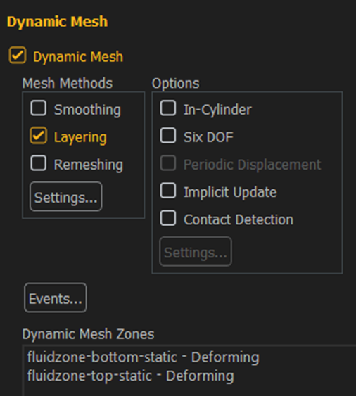
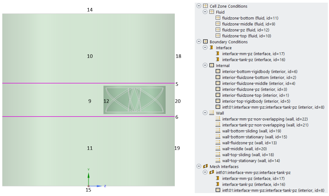
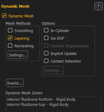
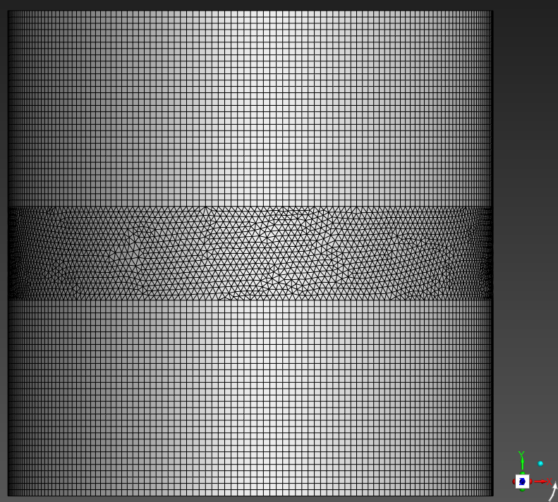
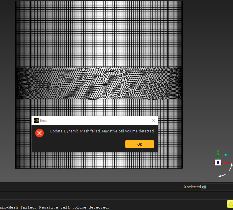
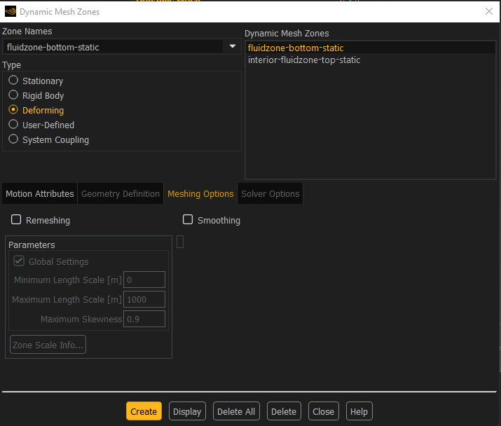
      I created two Dynamic Mesh Zones, one for the top and one for the bottom fluid zone and chose Layering only.

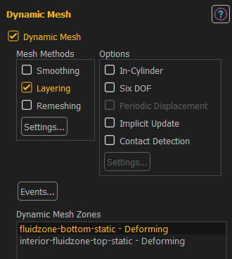
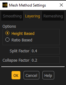
      When I click on the Settings for Mesh Methods, I see the Layering constants.

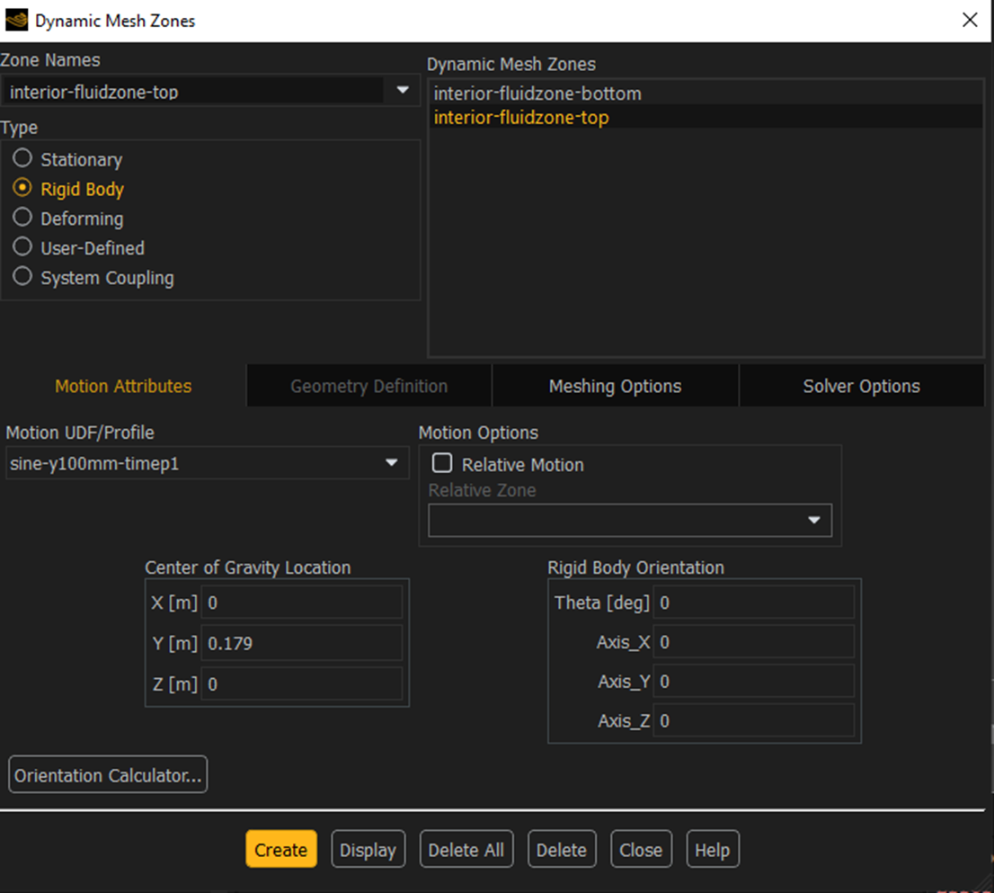
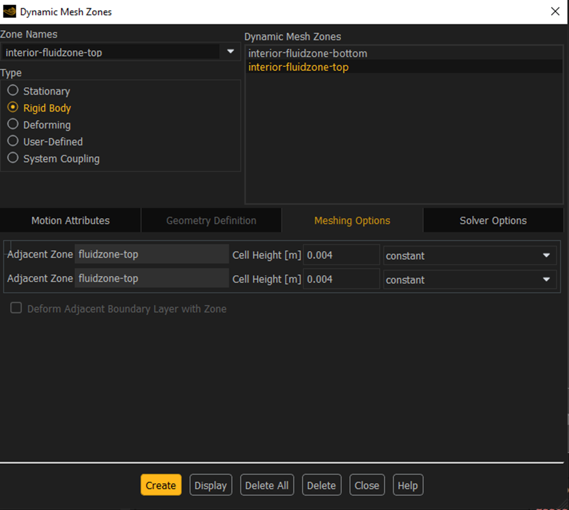
      Below is the dialog to set up one of the dynamic mesh zones. There is no Layering Option.

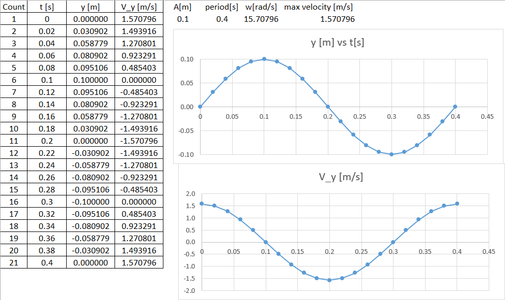
      In the Ansys How To video, one boundary on the Inlet zone has a Motion Profile that causes that boundary to move.

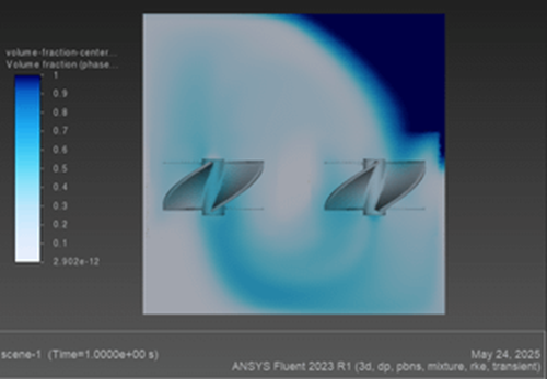
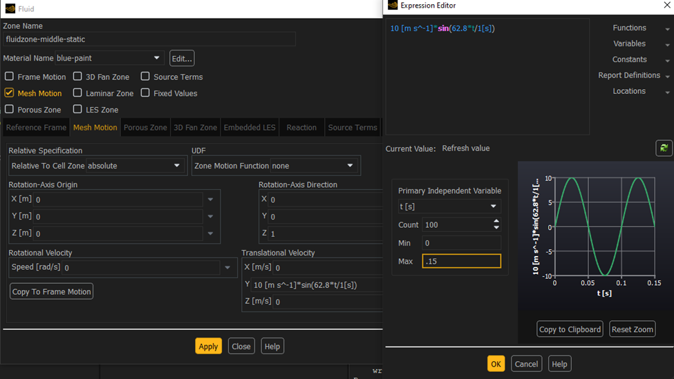
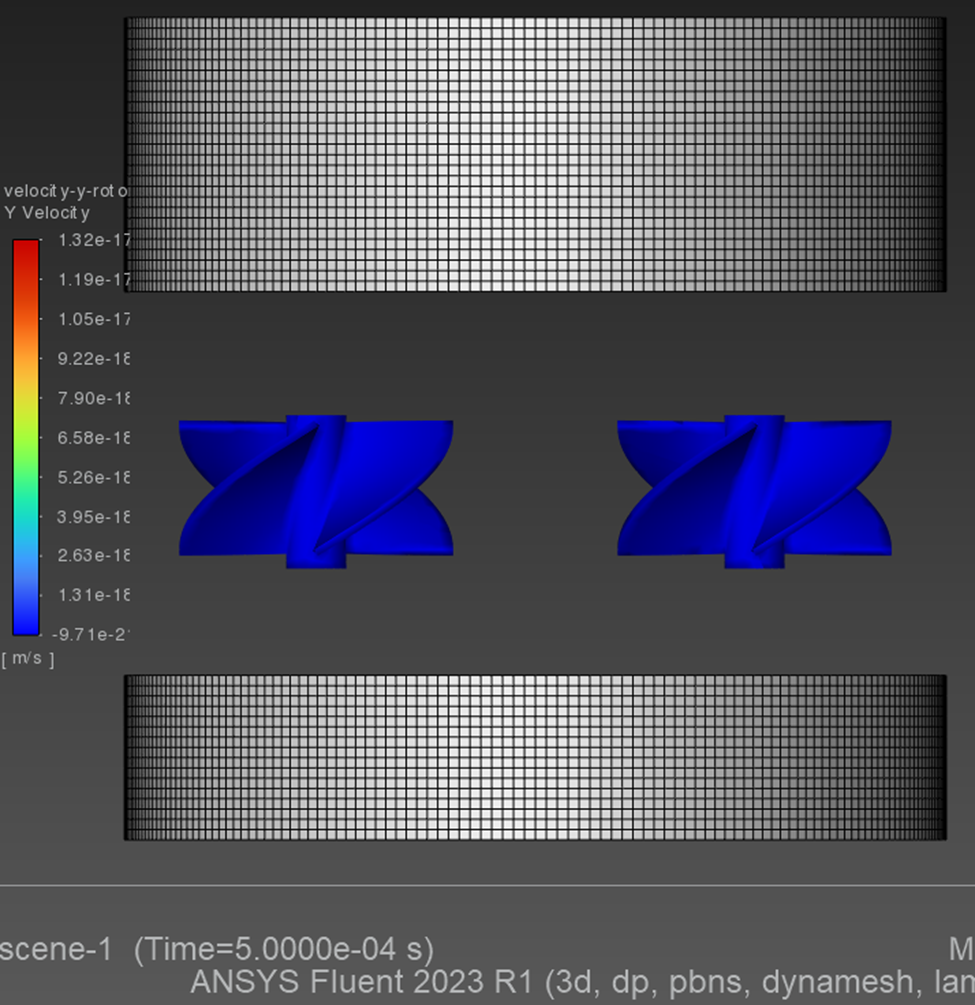
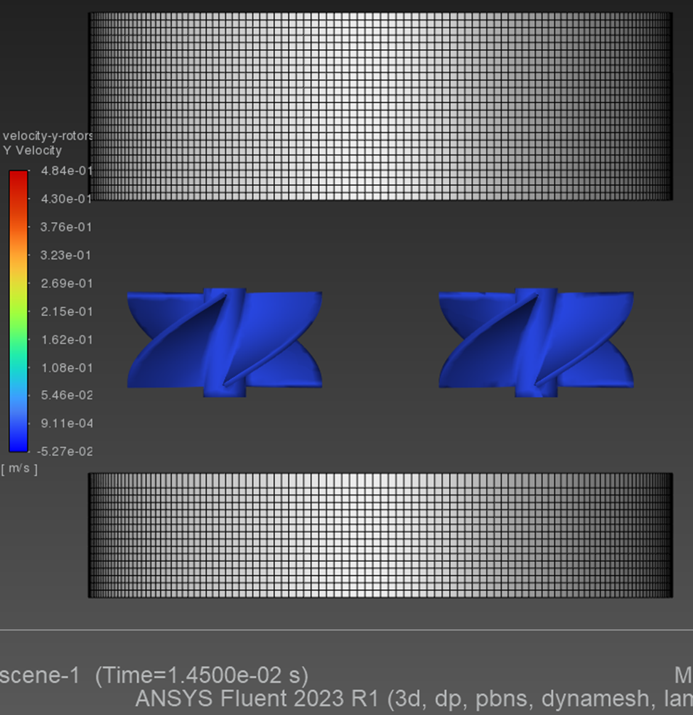
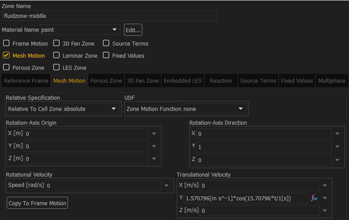
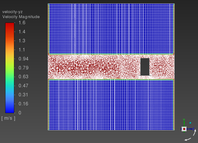
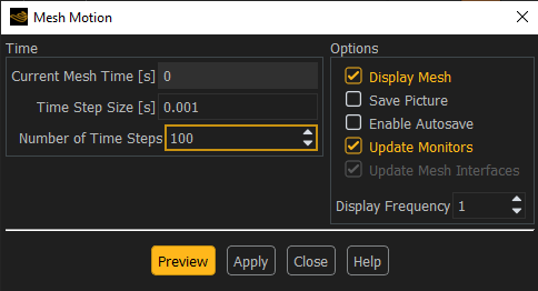
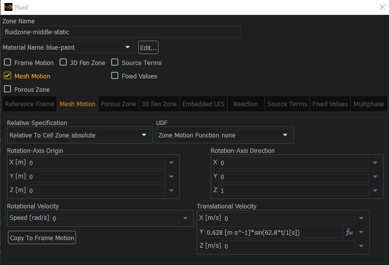
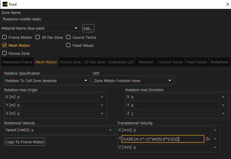
      In my example, I want the top and bottom zones to deform because the middle zone has a Mesh Motion cell condition.  So the face shared between the middle zone and the top or bottom zone is moved by the adjacent zone moving.  Below is the Mesh Motion setting on the middle zone.

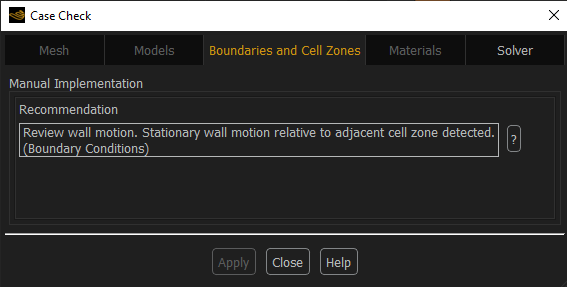
      You said “set the top and bottom boundaries as Stationary”.  Here are the Wall Boundary Conditions I currently have.

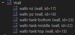
      The walls-tank-top is composed of two surfaces: a cylidrical surface and a flat circular top surface. That is currently set to Stationary Wall.

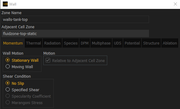
      You are suggesting that this should be separated into two wall boundary conditions so the top face can be left as stationary, but the cylindrical face, would that be defined as a Moving Wall?

      Same goes for the walls-tank-bottom boundary.

       “you should set each Layering cell zone with Rigid Body motion to follow the same motion as your sliding mesh in the middle.”

      The motion of the middle zone follows a sine expression. When I add a Dynamic Mesh Zone for the fluidzone-top-static and set it to Rigid Body, there is a box for Relative Motion, but it does not allow me to see any zones in the pull down.

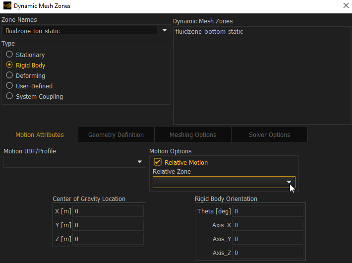
      I don’t have a Motion UDF/Profile because I used an expression directly in the Translational Velocity Y component for the middle zone condition.

      Please advise on the best path forward, thanks for your help.

    • Federico
      Ansys Employee

      Each layering cell zone should be set as Rigid Body Motion (with the motion following the oscillating sin expression). It will move the entire cell zone according to that expression.

      To set the location of the Layering collapse/split, you need to have a boundary zone for the Top wall and a second for the Bottom wall. Set them as Stationary in the Dynamic Mesh zone settings. When you do, go to their corresponding Meshing Options (still in the Dynamic Mesh Zone settings page) and define the Layer cell height.

      The mesh motion set for the inner zone with the sliding mesh can remain as you had previously set it up.

Viewing 3 reply threads
  • You must be logged in to reply to this topic.