TAGGED: adhesive, czm, midsurface, shell-elements
-
-
May 10, 2025 at 6:37 pm
Aymen
Subscriber
Hi everyone, I'm trying to implement a Cohesive Zone Model (CZM) in ANSYS Mechanical to simulate adhesive bonding between a shell element (mid-surface airfoil) and a solid body (square tube).
However, I’m struggling with contact activation and realistic adhesive behavior.
Setup:
- The airfoil is modeled as a shell (mid-surface) with 1 mm thickness, using Offset Type = Middle to activate the shell thickness effect in contact.
- Contact is defined as bonded (formulation: Augmented Lagrange), with contact shell face = bottom.
- Fracture behavior is activated via Contact Debonding = CZM, with material data from adhesive manufacturer "3M". The shell face is the contact, and the solid outer wall of the square tube is the target.
Problem:
- In the Contact Tool, the contact side appears as “Closed”, but the target side remains inactive
- The geometric gap is 0.5 mm, which matches the expected half of the shell thickness
- The default pinball radius is too small, and a warning in output always appears: "Normal separation at maximum traction for debonding (...) is greater than pinball radius (...) debonding calculations will be bypassed..."
- When I set the pinball radius to 0.6 mm (to match the gap), the warning still appears
- I’ve read that using a bonded contact with an enlarged pinball radius can artificially stiffen the interface and suppress damping behavior that adhesives would normally provide. So I'm unsure if this is even correct modeling.
- I also tried flipping contact/target sides, but the same result.
- Adjust to Touch is not available for bonded or CZM contact types.
- If I change the shell offset to bottom to match the contact geometry better, then Ansys no longer considers the shell thickness in the contact behavior.
So my question is how I can define the contact between a shell mid-surface and a solid face properly and avoid the solver warning. What I really want is to make sure the contact activates as expected and that the adhesive behavior, like debonding and frictional stress, is captured realistically.
I should mention that I already tested the same adhesive using CZM between two solid bodies, and in that case, everything worked fine, and the results matched the datasheet. -
May 13, 2025 at 1:41 am
Shashidhar Reddy
Ansys EmployeeHi,
”The bonded contact with an enlarged pinball radius can artificially stiffen the interface.” this statement is valid when you have target surface larger than contact surface. In this case, with increased pinball radius, the part of target that get bonded with contact increases at the boundaries of the contact surface. This results in stiffening of bonded contact. If you have exact overlapping contact and target surfaces, you dont need to worry about it. Otherwise, try to split the target surface geometry such that you can scope the target exactly as needed.
Yes, we can apply shell thickness effect only when we set the offset type to middle surface.
CZM requires the contact pin ball radius greater than the contact gap at the completion of debonding. So, make sure you are setting it appropriately. Further, if the target or contact is constrained only by the bonded contact, you may need to set the pinball radius larger than the gap between target surface (solid body) and middle surface of the contact (in your case >0.5 mm). Otherwise, it will give solver pivot or rigid body motion error.
Hope it helps. Please let me know if this clarifies.
Thank you
Regards
Shashidhar, PhD
ANSYS Introducing Ansys Assistant a 24/7 AI-powered virtual assistant for active Ansys academic customers.
-
May 15, 2025 at 6:41 am
Dennis Chen
SubscriberHello Aymen, if you consider your shell body with thickness effects turned on, is there a geometric gap between the solid and shell elements? ( I can’t tell 100% from the comments so want to confirm)
lastly, have you tried building a simple plate solid vs plate shell model, with and without any geometric gap between the 2 plates (after considering shell thickness) to see what the behavior looks like?
When I get a chance, I can try building this as well but it’s a good step to take to test out the behavior.
lastly, if your bond interface has adhesive of various thickness, a single CZM model will not properly cover the response because CZM model in essence covers the damage behavior which is heavily dependent upon the processing surface for the crack. most CZM material model are tested/calibrated based upon a specific bond thickness so if the model is tested based on 2mm thickness but your largest gap is a lot larger than 2mm, the damage behavior is no longer really valid along those region. It is something important to keep in mind.
Overall, I am a much bigger fan of having cohesive elements explicitly modelled like in Ls-dyna or abaqus but in the case of ansys mechanical, I think we want to dig deeper into how the contact debonding works at the smallest most foundational level, say between 1 element on the contact side vs 1 element on the target side, is spring being attached as they should in a penalty based contact? how is the separation in normal and tangential direction implemented based on the traction separation function. with this understanding, we can get a better sense of how different pinball radius may affect the behavior in the joint.
In that regard, I don’t have an answer yet but it is in my opinion a good question to ask.
Hope this helps.
-
May 15, 2025 at 12:10 pm
Aymen
SubscriberHi Shashidhar and Dennis,
Thanks again for the helpful input.
I set up the simple test cases you mentioned, using a solid/solid and a solid/shell configuration. The shell was placed with a ”middle” offset (1 mm thick), which resulted in a 0.5 mm geometric gap to the solid. I used a slightly increased pinball radius (0.6 mm) to cover that.
Both models used the same cohesive contact setup (DP490), same loading, same mesh density, and boundary conditions. The displacement and damage evolution were nearly identical in both setups. Even the frictional stress distribution looked the same. So at least in this controlled setup, the shell–solid combination with proper pinball radius seems to behave just as well as the solid–solid version.
(Just to clarify: in the attached plots, displacement is on the x-axis and stress on the y-axis; the labels were switched by mistake.);
-
May 15, 2025 at 1:03 pm
Aymen
SubscriberHey guys,
I’ve been running multiple simulations on the same model with different load cases, and there’s one issue that keeps coming back. It doesn’t always happen, which makes it even more confusing. In some load cases, the contact behavior looks completely fine, but in others, I get strange differences in how the contact stresses are displayed in the Contact Tool.
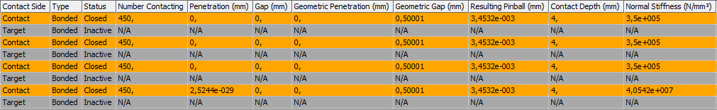
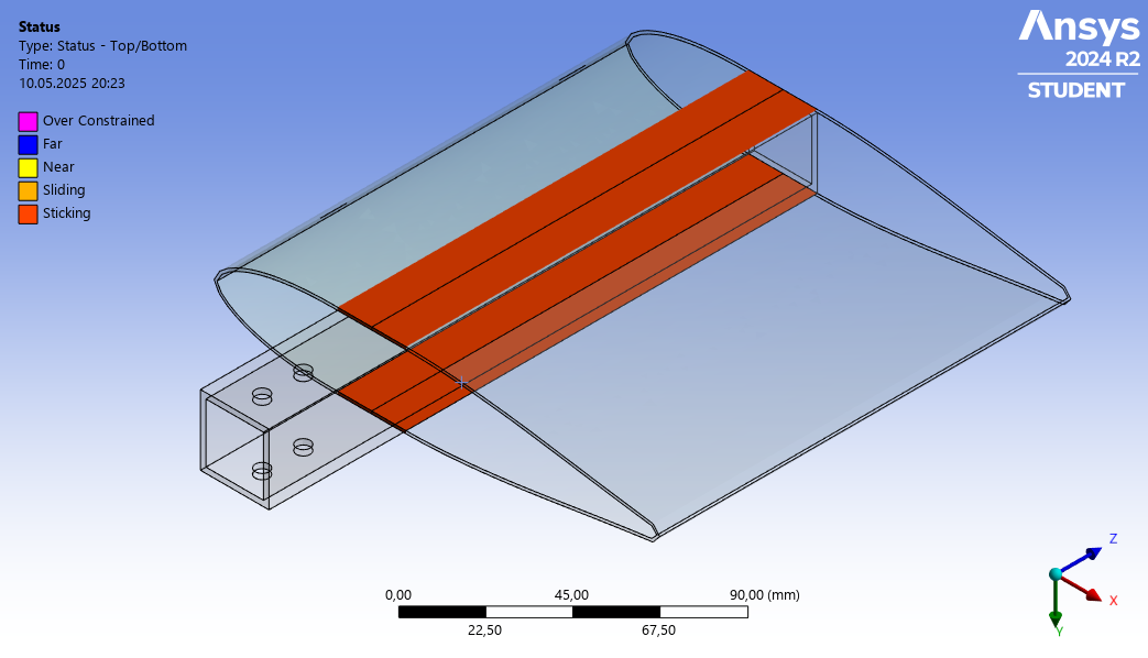
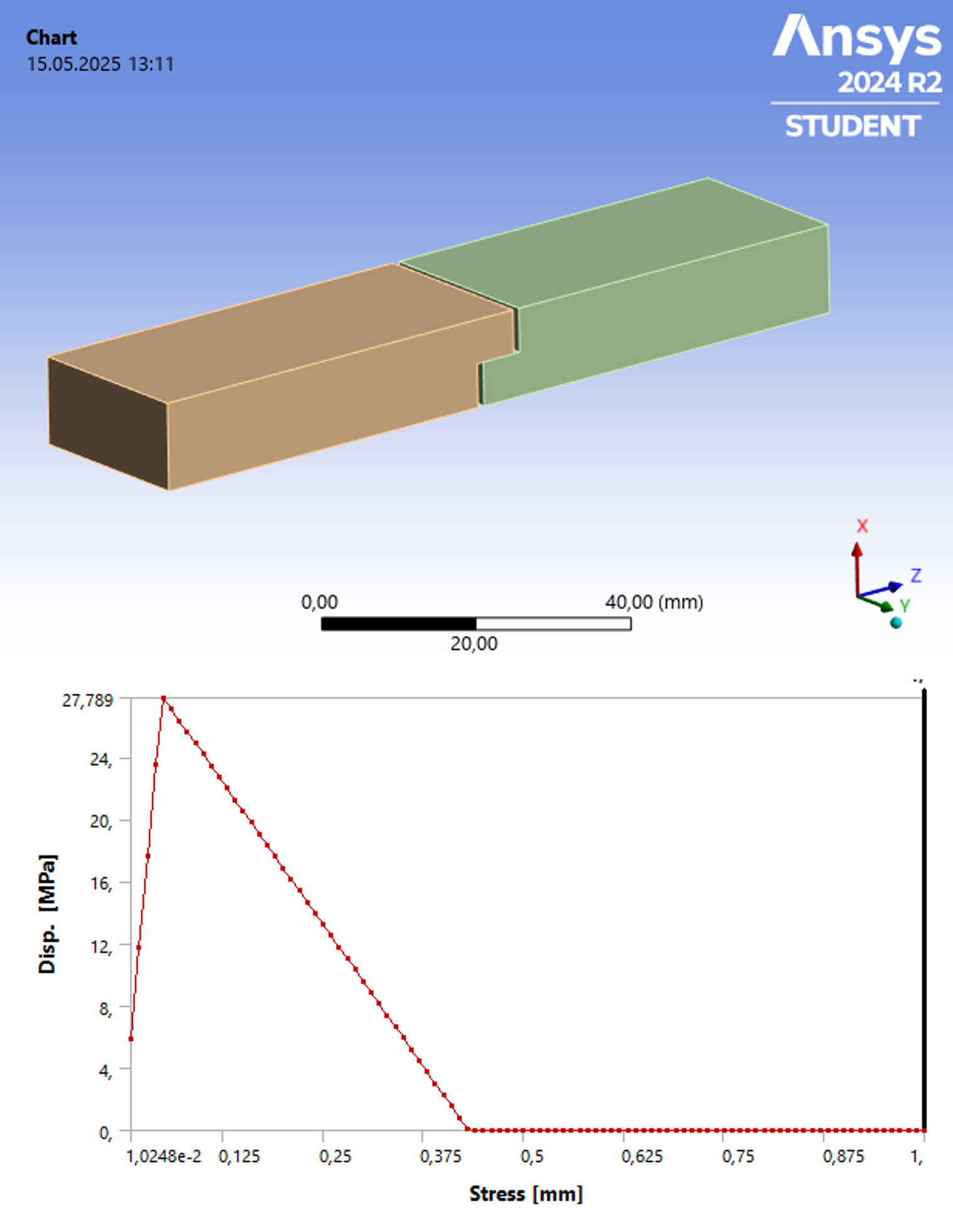
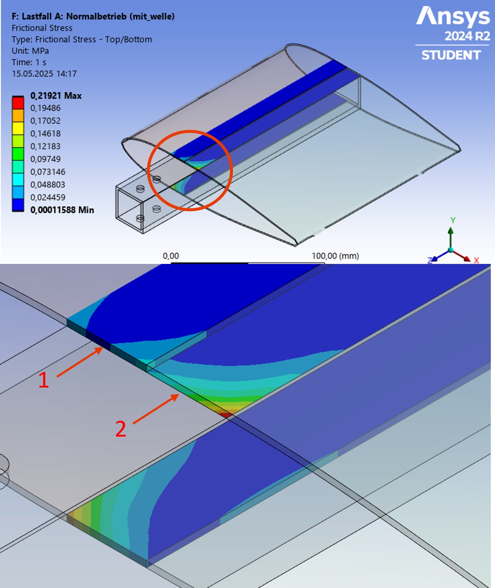
As shown in the attached image, in some simulations the frictional stress appears on the contact surface (marked as 1), while in others it shows up on the target surface (marked as 2). For me, the results shown on the target side (2) always feel more physically realistic. The stress distribution looks smoother, and the cohesive behavior is more consistent with what I expect, especially in cases involving separation.
The strange part is that all contact definitions are identical. Same contact type, same material models, same mesh size and refinement, and the same surface selections. I’ve even gone through the process of deleting all definitions and recreating them from scratch, just to be sure. In one case I even duplicated the working contact and just reassigned the faces, thinking it might help. But no matter what I do, this behavior randomly switches between simulations.
I’ve been trying to figure out what’s actually controlling whether the result ends up on the contact or target surface, but I can’t find any logic to it. I would really appreciate if someone has an idea what might cause this or if there's a way to force consistent output on one side. It would help a lot to understand what’s going on behind the scenes.
Thanks again for all the support and input so far.
-
- You must be logged in to reply to this topic.
-
3139
-
1007
-
923
-
858
-
792
© 2025 Copyright ANSYS, Inc. All rights reserved.