-
-
January 20, 2025 at 4:25 pm
bojan.nikolic.2
SubscriberDear Ansys support team,
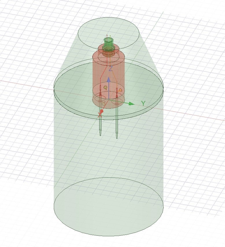
I'm seeking guidance on comparing impedance measurements obtained from Ansys Maxwell (AC Conduction and Eddy Current solvers) and HFSS. My simple model (Figure 1) consists of two metal pins partially covered by a plastic housing and partially immersed in a low-conductivity liquid (saline water with a conductivity of σ = 0.3 S/m). The housing and the top part of the pins are in air. The tops of the pins are connected to copper wires to which an AC voltage is applied, with frequencies ranging from 10 Hz to 100 MHz. This basic model will later be modified by replacing the saline water with materials of varying conductivities.
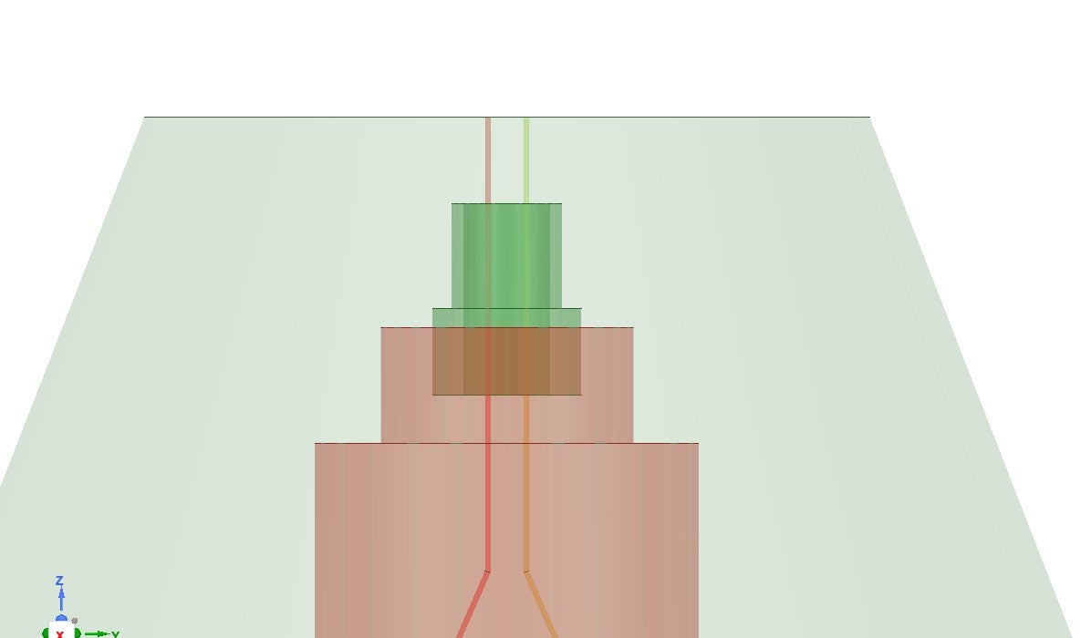
- I've successfully obtained results using the Maxwell AC Conduction solver. However, a very similar model in Ansys Eddy Current (Figure 2), where the connecting wires are extended to the model's edge and voltage is applied through terminals and windings, reports the following error:
Verify conduction path 'Path1': In one solid conduction path, at least two external terminals should be specified. Verify conduction path 'Path2': In one solid conduction path, at least two external terminals should be specified.
It appears Maxwell is incorrectly recognising the saline water as a non-conductive material in this case, leading to this error. When I changed the conductivity of the saline water from 0.3 S/m to 300 S/m, I didn't receive any error, and the simulation worked. How can I resolve this issue?
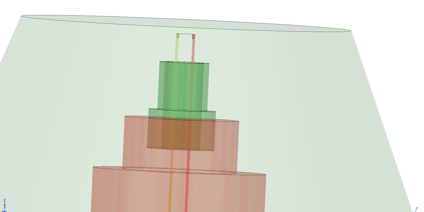
- Additionally, I'm a complete beginner with HFSS. I'd like to measure the impedance of the same model in HFSS. I've attempted placing lumped ports on the wires within the model (Figure 3), but I'm unsure how to extract the impedance values in this setup. Any tips on how to properly set up and extract impedance measurements in HFSS for this type of problem would be greatly appreciated.
Thank you for your time and assistance.
- I've successfully obtained results using the Maxwell AC Conduction solver. However, a very similar model in Ansys Eddy Current (Figure 2), where the connecting wires are extended to the model's edge and voltage is applied through terminals and windings, reports the following error:
-
- You must be logged in to reply to this topic.


- HFSS Incident Plane Wave excitement mode
- How to calculate eddy and hysteresis losses of the core?
- Ansys Maxwell 3D – eddy current
- Simulation of capacitor combining eddy currents with displacement currents
- dq graph non-conformity
- Simplorer+Maxwell Cosimulation results and Maxwell results mismatch
- Parametrizing coil “terminals” with coil geometry
- Maxwell circuit – PWM
- Plotting Ex, Ey and Ez in vector forms individually
- Calculating E-field tangential to a 2D resonant structure on a sapphire chip

-
1882
-
802
-
599
-
591
-
366

© 2025 Copyright ANSYS, Inc. All rights reserved.


