TAGGED: constraint-issue, fsi, transient-structural, turbine, turbomachinery
-
-
May 2, 2025 at 7:11 am
vedangbhosale2002
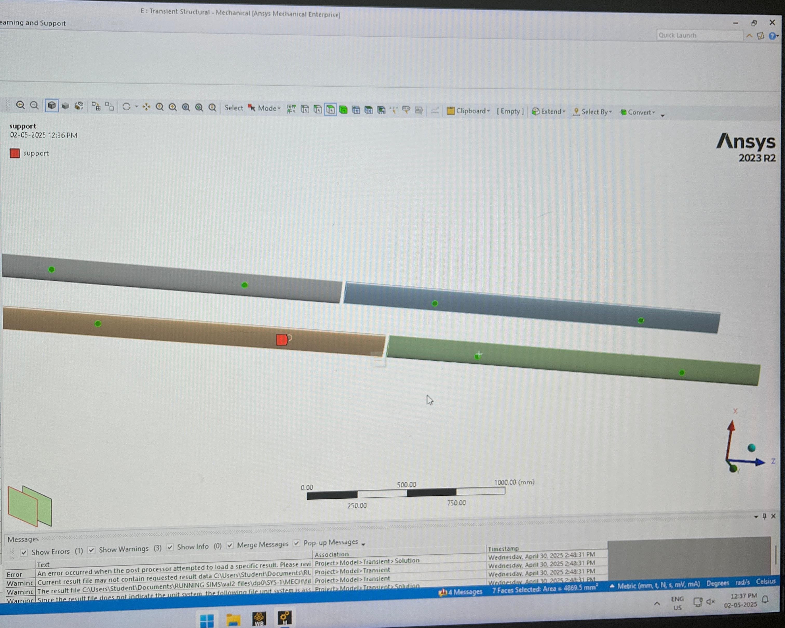
SubscriberHello everyone,I’m currently working on a one-way FSI simulation(before moving on to two way) of a contra-rotating vertical axis wind turbine (CR-VAWT) with 4 extended blades (2 clockwise, 2 counterclockwise), rotating about the Z-axis. I'm using Fluent for pressure loading and Transient Structural in Workbench 2023 R2.Since Fluent does not transfer centrifugal effects in a one-way FSI setup, I’ve manually applied Rotational Velocity (Z-axis) to both turbine blade sets in Transient Structural to account for internal body forces. Each turbine is modeled separately and shares a central axis at the origin.To avoid over-constraining the rotation and to replicate the realistic shaft support, I created a Remote Point at the origin, connected to 8 edge selections (circular edges), and applied a Remote Displacement boundary condition:UX, UY, UZ = fixedROTX, ROTY = fixedROTZ = freeThe idea is to allow rotation about Z while constraining the structure properly.However, when I run the setup, I get an error:> “The geometry is not constrained properly”> or the solve diverges immediately.When I apply Fixed Support at the base instead, the model solves — but deflection is unrealistically high due to improper physical constraints (blades should rotate freely, not be fixed rigidly).*Questions:*1. Is this Remote Point + Remote Displacement strategy correct for simulating rotating blades in FSI?2. How should I properly constrain the system to allow rotation and avoid rigid body motion errors?3. Is there a better way to apply Z-rotation freedom without compromising stability?4. Would weak springs or joints between the blades and the hub help in this case?Any guidance or examples for correctly constraining a CR-VAWT in one-way or two-way FSI would be greatly appreciated.
-
May 2, 2025 at 10:44 am
Rob
Forum ModeratorIf the blades aren't flexing can you use sliding mesh in Fluent and an Expression or UDF to convert pressure/force on the blades to speed?
-
May 2, 2025 at 2:48 pm
vedangbhosale2002
SubscriberHi Rob, thanks for the suggestion!
The main issue I’m facing is with the Structural boundary conditions in the one-way FSI setup. I’m applying pressure from Fluent in Transient Structural and using a Remote Point with Remote Displacement (UX, UY, UZ, ROTX, ROTY fixed, ROTZ free), along with Rotational Velocity to simulate centrifugal effects.
However, the simulation either diverges or reports under-constrained geometry. Using Fixed Support solves it, but it’s physically incorrect for rotating blades.
I’m looking for the correct way to constrain the blades while allowing Z-rotation and maintaining numerical stability.
Appreciate any advice!
-
-
May 2, 2025 at 2:52 pm
Rob
Forum ModeratorI'm assuming the above means the axis is fixed and that the blades can't move in the axial direction? What limits the rotation speed in Mechanical? Note, I'm not a Mech user, nor have much experience with FSI.
-
May 4, 2025 at 8:32 pm
vedangbhosale2002
SubscriberYes, the axis (Z) is fixed, and the blades are rotating about it. In Mechanical, I’m manually applying the rotational velocity to simulate the centrifugal effect since Fluent doesn't pass that force in one-way FSI. There's no dynamic speed update, t's fixed input per TSR case.The main challenge is properly constraining the blade roots: I want to prevent rigid body motion while allowing realistic blade deformation and rotation. Let me know if you have thoughts on stabilizing such a setup.
-
- You must be logged in to reply to this topic.


-
3266
-
1036
-
1004
-
859
-
798

© 2025 Copyright ANSYS, Inc. All rights reserved.


