Hello everyone,
I'm currently using ANSYS Fluent to simulate the aerodynamic behavior of a propeller using a rotating domain (MFR approach). While setting up the boundary conditions, I tried two different configurations:
1.One inlet and one outlet
2.Two outlets only (no inlet defined)
The geometry and mesh remain identical in both cases. However, I observed that the simulation results from Model 2 (two outlets only) are much closer to the physical behavior I expect and align better with experimental data — particularly in terms of pressure distribution, velocity field, and total thrust. In contrast, the results from the one-inlet-one-outlet setup deviate significantly.
I’d like to ask the community:
Why do the simulation results differ so noticeably between these two boundary setups, even though the flow direction is similar?
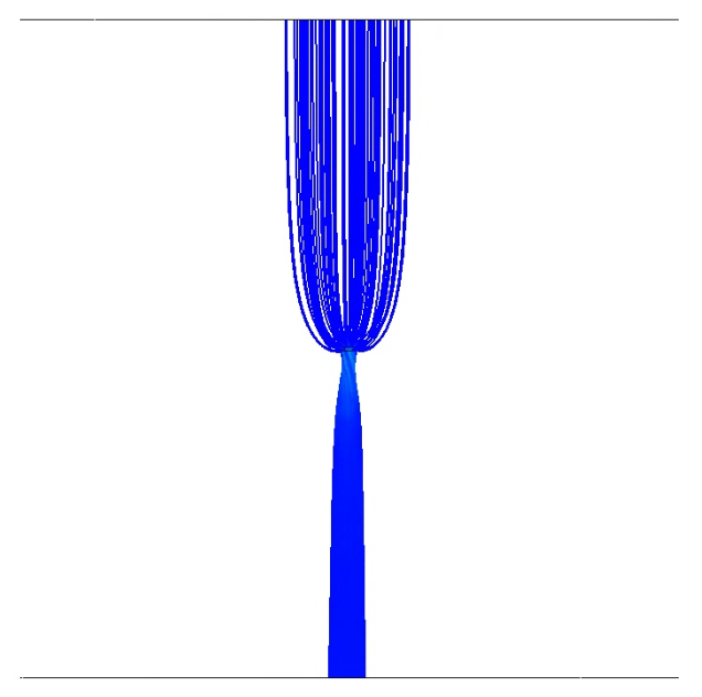
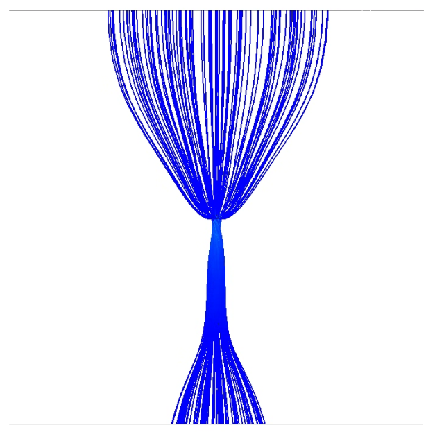
I've attached comparison images showing the results from both boundary condition setups.
The first image shows the results from the one inlet + one outlet case.
The second image shows the results from the two outlets only case.
As seen in the figures, the flow field and pressure distribution in the two-outlet configuration appear more physically realistic and better match experimental expectations. Any feedback or suggestions based on these results would be greatly appreciated. Thank you in advance!