-
-
April 25, 2025 at 2:40 pm
bryan10611015
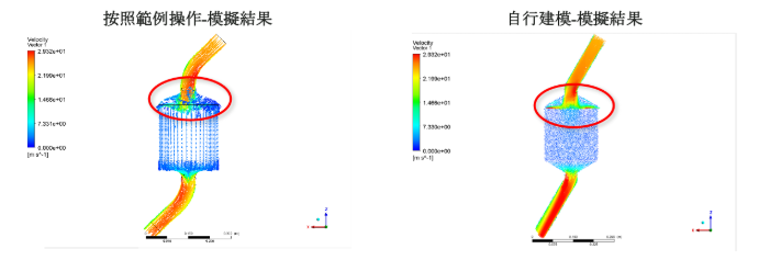
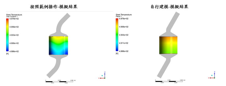
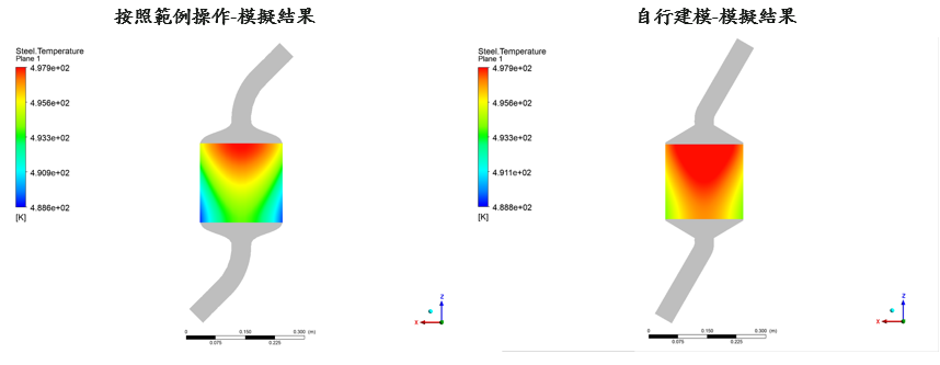
SubscriberHello, since my settings are all based on the Ansys example file, only the modeling and mesh cutting are done by myself. The size of my central catalyst area is 20*20*20cm, and the temperature and velocity fields in the central catalyst area are obviously different. I would like to know why there are differences in temperature and velocity fields. I would like to know if there are other reasons, or is it because of the difference in mesh or geometric structure? Since the Ansys CFX example cannot download the geometric size and mesh data, it can only be set from the Ansys CFX Pre file, so I cannot compare. I would like to ask for a solution. The following is my simulation result, thank you.
-
April 30, 2025 at 6:55 am
CFD_Friend
Ansys EmployeeHi,
Please check the mesh and see if there is enough resolution in the regions expected to have higher gradients. Perform a mesh independence test.
-
- 必須登入。


-
3024
-
971
-
857
-
831
-
777

© 2025 Copyright ANSYS, Inc. All rights reserved.


