High-Lift Devices: Air Flow over a Three-Element Airfoil - Simulation Example
Overview
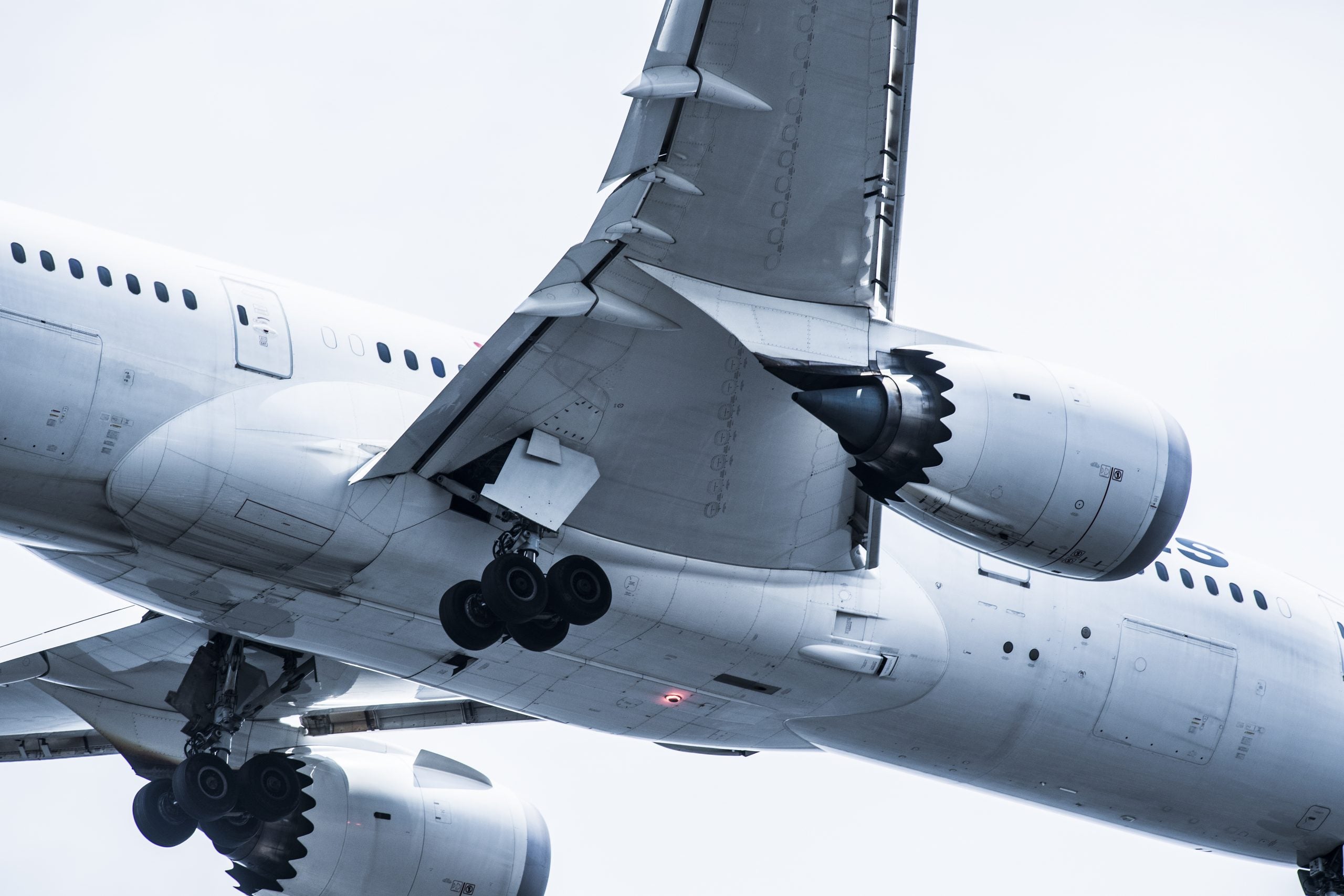
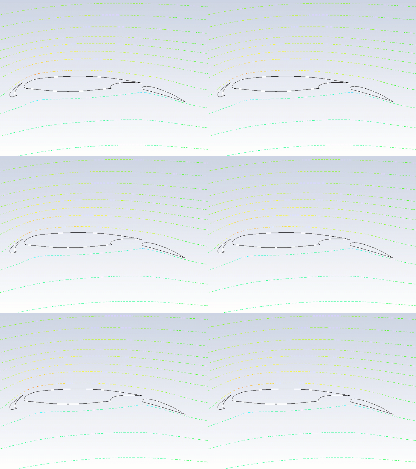
High lift devices such as slats and flats are used on large commercial aircraft to generate a larger lift force. Slats are aerodynamic structures at the leading edge of the wing and flaps are deployed at the trailing edge. By controlling the distance between these structures and the main airfoil as well as their orientation, commercial aircraft are able to generate more lift at reduced airspeeds during take-off and landing, thus requiring shorter runways. Furthermore, the deployment of these elements also increases the drag force, which is incidental but helpful in slowing the aircraft down during its landing approach. When the aircraft is at cruise altitude, the slats and flaps are retracted into the wing. In this simulation example, we will understand the impact of flaps and slats on lift and drag forces. The 2D, three-element airfoil configuration comprises a fully deployed slat, main airfoil and flap.
Objectives
In this simulation example, we will learn how to simulate the air flow over the three-element airfoil using Ansys Fluent. We will estimate lift and drag forces for this configuration. We will also compare these values with those from the case without slats or flaps. The angle of attack (AoA) is 4 degrees and the freestream Mach number is 0.19.
Setup
Download the Mesh file required for setting up the simulation and associated Case & Data files here. Follow the instructions below to set up this simulation in Ansys Fluent starting with the Mesh file. In case you face any issues setting up or running the simulation, refer to the corresponding initial and final Case and Data files.
Results & Discussion
Let’s now take a look at the results to understand the lift and drag forces generated on the airfoil.


