Animate HMI using a Logic Code using SCADE — Lesson 3
Aim: Create a logic for a counter using SCADE Suite and integrate it with the HMI code.
3. A. Create the Folder Structure
We will be creating a SCADE Suite program to create a counter and interface the program with the SCADE display code.
- Create three folders: one for the SCADE Suite project, one for the SCADE Display project, and one for generated code.
 Figure 3a: Recommended folder structure for the working project
- Copy the SDY project (FlightControlDisplay folder) to the folder location.
- Create a new SCADE Suite project to create a counter to increment roll and pitch value as in the next step.
Note: Skip steps 1-3 if you use SCADE Suite and Display projects from SS and SDY folders respectively from this link.
3.B. Create the Logic using SCADE Suite
Note: Skip steps 3-10 if you use the model from the SS and SDY folders under Lesson 3.
- Create a SCADE Suite model (for example, FCS_Pi) with two outputs pitch_angle and roll_angle. This model does not have any inputs. You can find the model in the SS folder under Lesson 3.
- Create a counter to increment the value of pitch_angle and roll_angle.
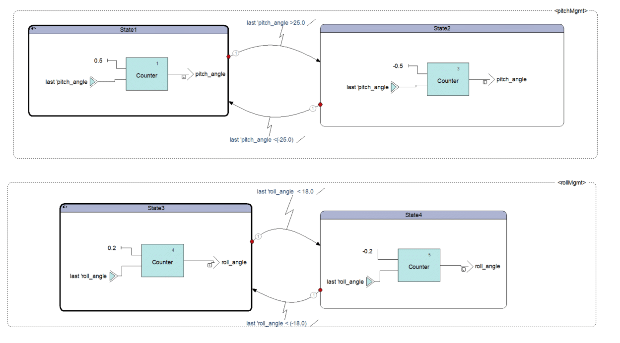 Figure 3b: SCADE Suite Model for creating a counter to change the value of pitch and roll
- Drag and drop the SCADE Display ETP file (e.g., DemoPFD.etp) in the File View of the SCADE Suite project:
 Figure 3c: Adding the SCADE Display file to the SCADE Suite model
- Select "KCG" under settings
 and click on the Settings button.
 - Set Root Operator (for example, pitch_roll_counter).
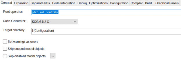 Figure 3d: General configuration settings for pitch_roll_controller
- Under Code Integration > Adaptor, select SCADE Display Co-generation.
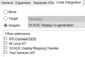 Figure 3e: Code integration configuration Settings for pitch_roll_controller
- Under the Graphics panels, select PF2 configuration as Code Generation (press F2 to enable the change).
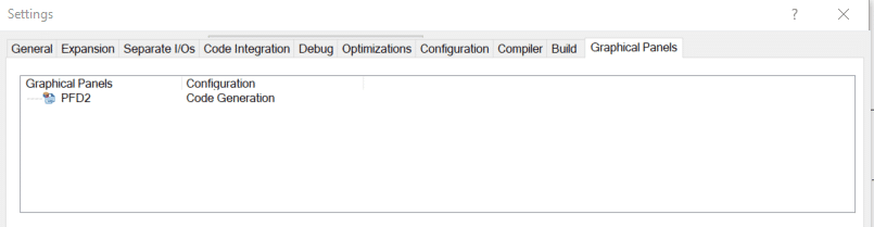 Figure 3f: Graphic panels configuration Settings for PFD2
- Under SCADE View, right-click on the pitch_roll_controller operator and select "Connect to Graphical Panels."
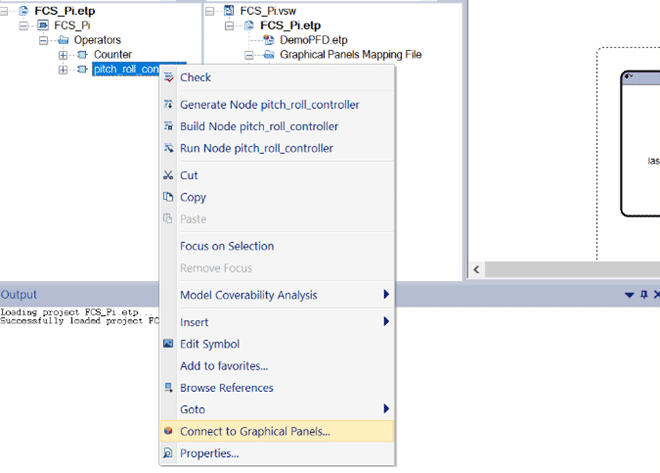 Figure 3g: Snapshot of selecting the option "Connect to Graphical Panels" for pitch_roll_controller
- Connect pitch_angle to PN_PITCH_ANGLE and roll_angle to PN_ROLL_ANGLE in the Graphical Panels.
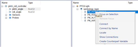 Figure 3h: Connecting SCADE Suite components to SCADE Display components
- Connections will look like the following:
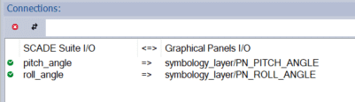 Figure 3i: SCADE Suite components connected to SCADE Display components
- Save the model and generate the code.
3.C. Prepare Files on the Host to Copy
- Copy all the .c and .h files from the generated SCADE Display and SCADE Suite projects into the code folder.
- Copy the kcg_assign.h file from the install folder location into the code folder.
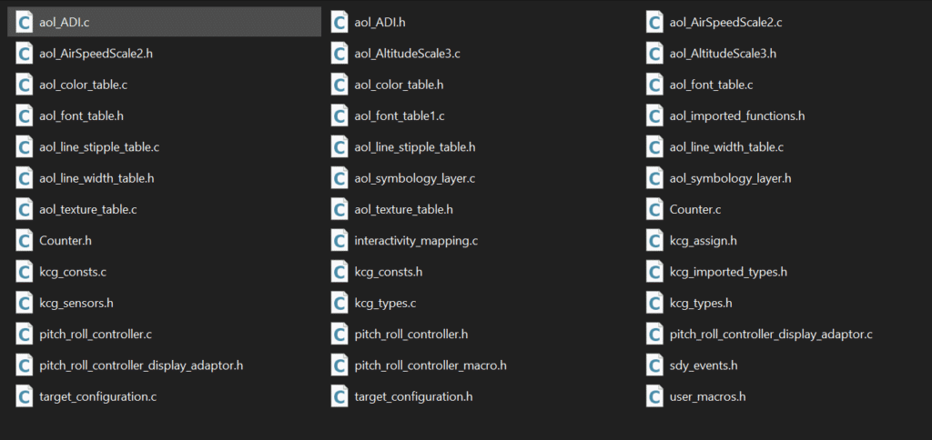 Figure 3j: Folder structure of the .h and .c files copied into the code folder
3.D. Configure the Files on the Raspberry Pi
- Create a copy of the PiPFD folder on Raspberry Pi and call it PiPFD_Counter.
- Copy this folder to Raspberry Pi under the code folder in PiPFD_Counter as showcased in Lesson 2.
- Delete the code folder already existing in the PiPDF_Counter. The newly generated code from the above section will be copied here.
- Open the specific.c file under the src folder and add the following line under init_scene(). Add this line after #if defined(COEXECUTION) and before Reset();
-
draw_init(); - line 223
-
Note: You can skip step 3 if you use files from this folder.
- Execute the following command in the Raspberry Pi command Window:
-
-
gcc -o out main.c specific.c ../code/*.c ../../../extras/utils/src/*.c
../../../lib/libOGLX.a -I../code/ -I../src/ -I../../../include/
-I../../../extras/opengl/ -I../../../extras/utils/include
-DCOEXECUTION -L/usr/lib -lX11 -lGL -lglut -lm
-
The only option that changes here from step in Lesson 2 is that we have a -DCOEXECUTION flag.
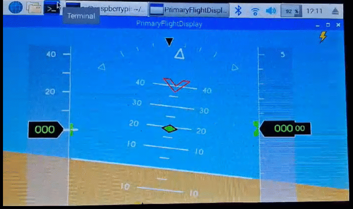
- Run the out file using the command ./out. You will observe the executable runs in co-execution mode as follows:
You are being redirected to our marketplace website to provide you an optimal buying experience. Please refer to our FAQ page for more details. Click the button below to proceed further.