Accuracy and Performance Tips Using Ansys Lumerical DGTD — Lesson 1
Adding Materials
Accurate modeling of optical materials is key to simulation accuracy in an optical simulation. In a DGTD simulation, materials are set as a property of a geometric object. The default material database includes sampled data for common materials in the optical wavelength range from references such as Palik, CRC, and Johnson & Christy. It is also possible to add new materials to the database.
Using materials in a DGTD simulation is a three-step process. First, ensure the desired material exists in the Material Database. Next, create an instance of the material in the Object Tree, in the "materials" section of the tree. Finally, associate geometric objects with the model materials. The following video will walk you through the process of adding materials to your simulation in the Finite-Element IDE and is applicable to all the available solvers, not just DGTD.
Material Fitting

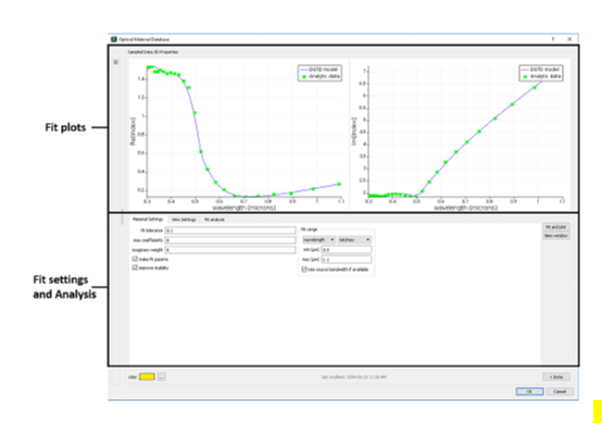
When using the sampled data material model, it is always necessary to generate an analytic fit of the sampled data. This is done using Lumerical’s multi-coefficient material (MCM) model. The fit can be visualized and adjusted using the material explorer. The material explorer can be opened from the optical material database window. Before simulating, it is always a good idea to check the model (fit) with the material explorer. If the fit is not very good, fit parameters can be adjusted. The material explorer controls are divided into three tabs:
Material settings: This tab contains fit settings for the multi-coefficient material model such as fit range and tolerance.
View settings: These settings can be used to customize the fit results plots displayed in the material explorer window.
Fit analysis: Provides goodness of fit merits to evaluate how close the fitted model is to the sampled data.
For a detailed description of the material models, fit setting parameters and fit analysis results, please visit the related links listed below.
Boundary Conditions
In this video lesson, you will learn about various boundary conditions available in the DGTD solver. The simulation files used in the video can be downloaded below:
DGTD_Optical_Disk_Metamaterial.ldev
DGTD_Optical_Disk_Metamaterial_Symmetry.ldev
To visualize the results (normalized reflection vs. wavelength):
- Right-click the "R" monitor in the objects tree.
- Select "visualize -> flux."
- In the visualizer window, remove all the attributes except "T_back" and switch the parameter of the attribute from "f" to "lambda."
Simulation Performance
In this video lesson, you will learn about various simulation settings that can affect the overall performance of the simulation.
Convergence Testing
Numerical simulations always involve a trade-off between simulation time and accuracy. Increasing the accuracy tends to make the simulation time longer. It is important to understand the sources of numerical error and the steps that can be taken to reduce these errors to an acceptable level. It is important to consider what the acceptable level of error is for your simulation so that you can run your simulations as quickly as possible. The process of finding simulation settings that offer an acceptable level of error with the minimum simulation time possible is usually referred to as convergence testing. In this unit, the most important tools available in a DGTD simulation to perform convergence testing are reviewed.
Simulation mesh: level of refinement
The level of refinement of the mesh grid for the simulation can affect the accuracy of the results and the required simulation time. While a more refined mesh would generally provide more accurate results, it also lengthens the simulation time. The global mesh refinement in a DGTD simulation can be adjusted by the “Edges per wavelength” setting available in DGTD solver settings. In addition, if required, the mesh can be locally refined in the areas of interest using the Mesh Constraint objects. This can help to avoid over-refinement of the mesh in the areas that do not significantly affect the simulation results. For more information about mesh refinement tools and settings see the related links below.
Polynomial order
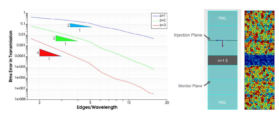
The order of the basis function used by the finite-element solver affects the accuracy of the results and the length of the simulation. A higher polynomial order can reduce the numerical error for a given mesh size, but will increase the time required to perform the simulation. The graph below demonstrates this concept by comparing the error in simulated transmission results for a 400-nm-thick glass slab. This indicates that for the same level of mesh refinement, higher polynomial order will result in more accurate results and the slope of the reduction in error with increased mesh refinement becomes steeper.

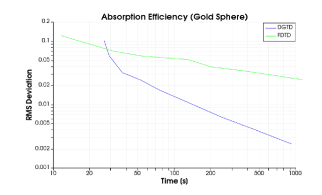
When it comes to comparison with FDTD, DGTD can achieve the same level of numerical error in a shorter time in most cases. This has been demonstrated in the plot below for the Mie scattering problem for a gold nanoparticle.

It is recommended that you run your initial simulations with "low" accuracy settings, so the simulations run quickly. At the beginning of a project, you will need to make many adjustments to simulation settings. This is much easier when the simulation runs quickly. Convergence testing should be done after the simulation is set up and you are getting reasonable results.

