-
-
January 14, 2021 at 3:00 pm
Jose1702
SubscriberHello, I am a mechanical engineer student. The subject of my research is to study the mechanical response of tensile probes with different infill patterns (Hexagonal honeycomb, Triangular honeycomb, Square honeycomb) and then compare the results of the simulations to define the better option for an optimal strength/weight ratio for a 3D printed part.
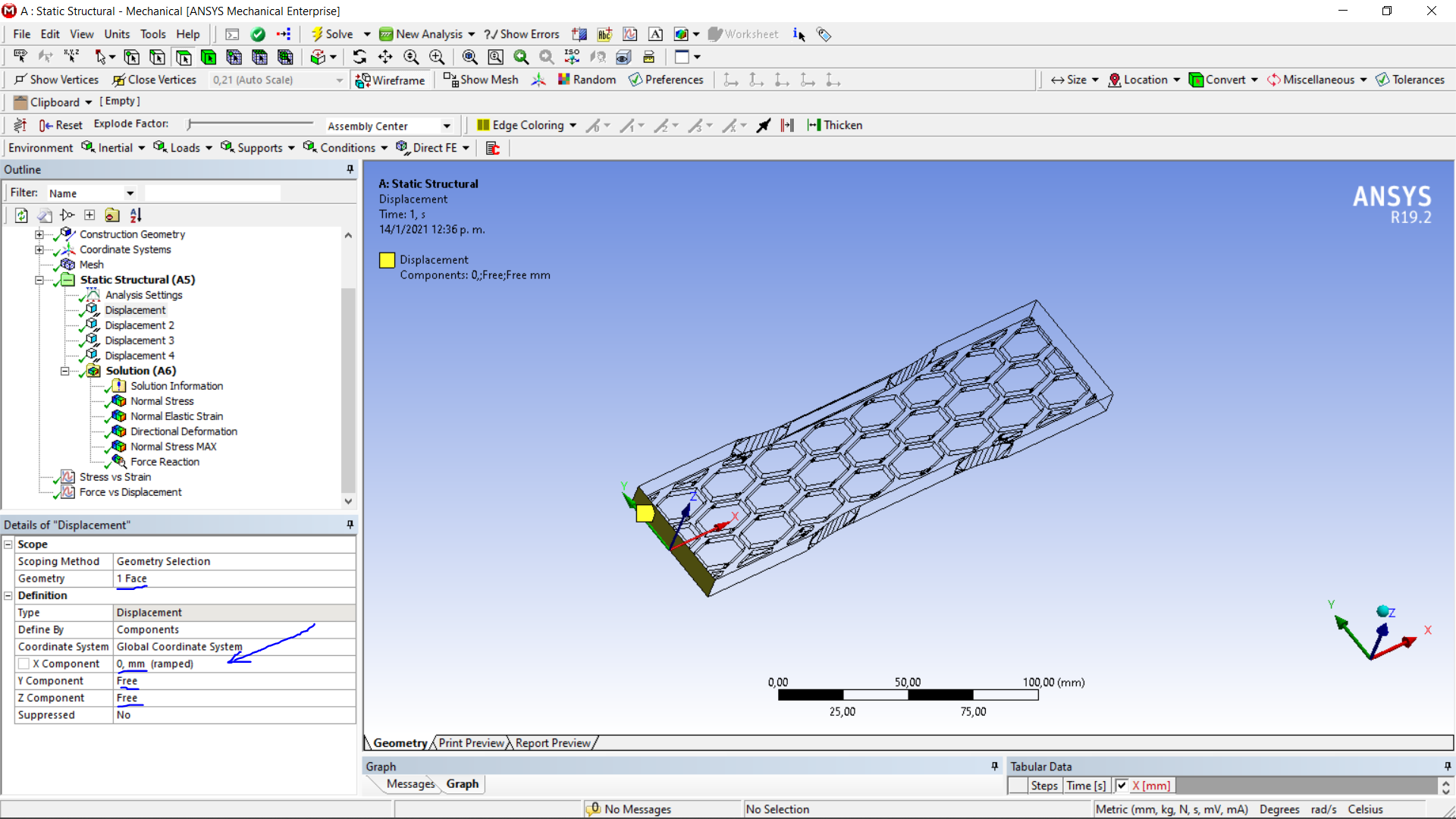
All specimens will be subjected to a Tensile stress test in Ansys WB using Static Structural, where I defined the same material and boundary conditions. The material is PLA. I leave images to illustrate the boundary conditions used in the simulation for the case of the probe with Hexagonal Honeycomb. The specimen's right end has a displacement of 2 [mm/min], as seen (I used tabular data to apply 2 [mm] displacement divided into 60 steps).
I would like to ask you if these are the correct boundary conditions. Because I had incorrect results with other conditions, and these seem to give acceptable results. For some reason I cannot explain when I was doing a mesh convergence study (reducing the size of my mesh elements), the values of the Stress never converged. For these conditions I used on my model, I did not experience this problem. If someone could explain to me why I had this problem, I would be very grateful. The boundary conditions that gave me such a problem where using Fixed support for the left end and a prescribed displacement or a load on the right end.
The thing is that the boundary conditions I used for the case I'm showing on the pictures should be used If the part had symmetry on those planes I applied them. And this is not my case, since the tensile probe I'm analyzing is the complete solid part and not 1/4 using symmetry for the analysis.
January 15, 2021 at 9:40 amAniket Chavan
Forum ModeratorAre you doing an actual experiment to check the results on these specimen? I am asking this because you said that you got incorrect results with fixed support and getting ok results with current setup of using BCs. If yes, how are you constraining the specimen in reality?n-AniketnHow to access Ansys help linksnGuidelines for Posting on Ansys Learning ForumnJanuary 15, 2021 at 10:39 amSubscriberThank you for your response kind Sir. The laboratory of my university was going to carry out stress tests on the 3D printed probes but in the end, they will not be carried out since they are currently closed due to the Covid crisis. nIn any case, the real conditions in which the tension machine would apply the tension test are grasping the flat ends of the left side of the specimen (grasping only the two opposite faces with the largest surface area) and pulling the other end applying a displacement of 2 [mm] per min. The right end is also gripped in the same way. I leave two images that illustrate the boundary conditions that I just mentioned.n
 nIn the subsequent images where I show the results obtained, I obtain a stress concentration right on the line that separates my fixed constraint from the center of the part, where the smaller section should experience the maximum stress. Also, I get absurdly high values for a 2 [mm] displacement in a PLA (a relatively flexible plastic) specimen.n
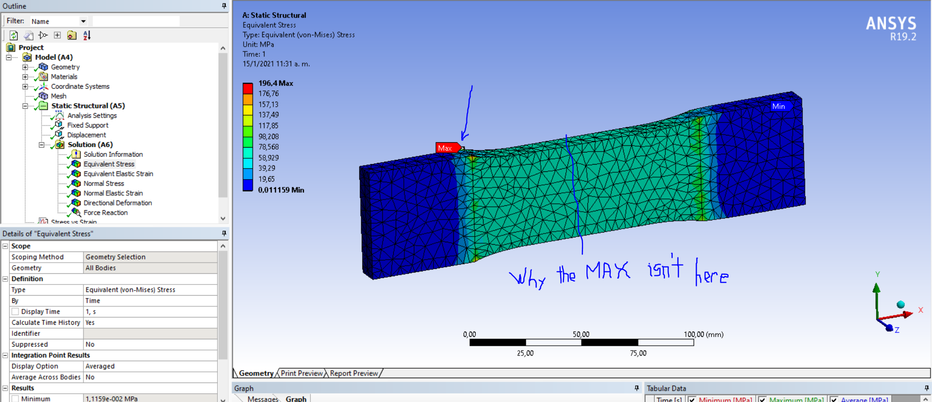 nFurthermore, I did a study of mesh convergence (reducing the size of the mesh elements) and the Equivalent stress values varied a lot in each step. The last image proves it.n
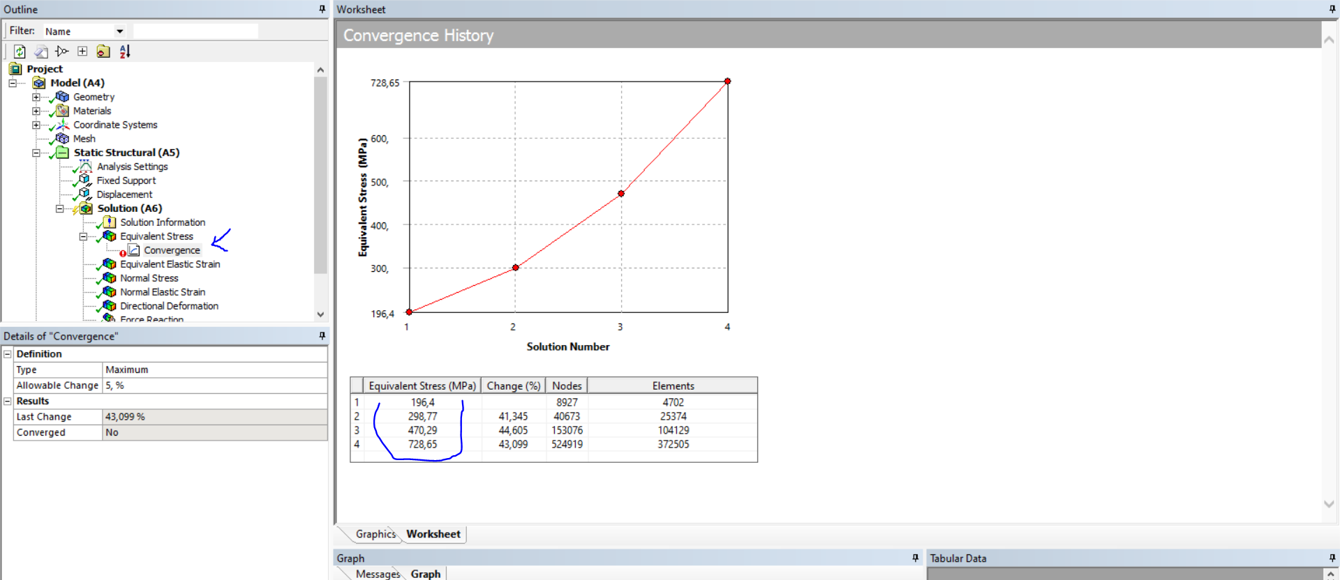 Could you explain to me why I have these results? Thank you very much in advance.
January 15, 2021 at 6:15 pmForum ModeratorAre you using nonlinear material properties? Also, I think what you are seeing at the edge is a singularity, so it will go on increasing as you refine the mesh.nWhat you can do (If your model is symmetric) is slice the model by planes parallel to XY and YZ plane. And apply 2 symmetry conditions and pull one end by half the displacement. This will be equivalent to pulling opposite ends by actual displacement in the full model.n-AniketnHow to access Ansys help linksnGuidelines for Posting on Ansys Learning ForumnJanuary 16, 2021 at 8:52 amSubscriberHi, I'm not using nonlinear material properties, I'm using Polylactic Acid (PLA) from the Ansys WB material library. n
Could you explain to me why I have these results? Thank you very much in advance.
January 15, 2021 at 6:15 pmForum ModeratorAre you using nonlinear material properties? Also, I think what you are seeing at the edge is a singularity, so it will go on increasing as you refine the mesh.nWhat you can do (If your model is symmetric) is slice the model by planes parallel to XY and YZ plane. And apply 2 symmetry conditions and pull one end by half the displacement. This will be equivalent to pulling opposite ends by actual displacement in the full model.n-AniketnHow to access Ansys help linksnGuidelines for Posting on Ansys Learning ForumnJanuary 16, 2021 at 8:52 amSubscriberHi, I'm not using nonlinear material properties, I'm using Polylactic Acid (PLA) from the Ansys WB material library. n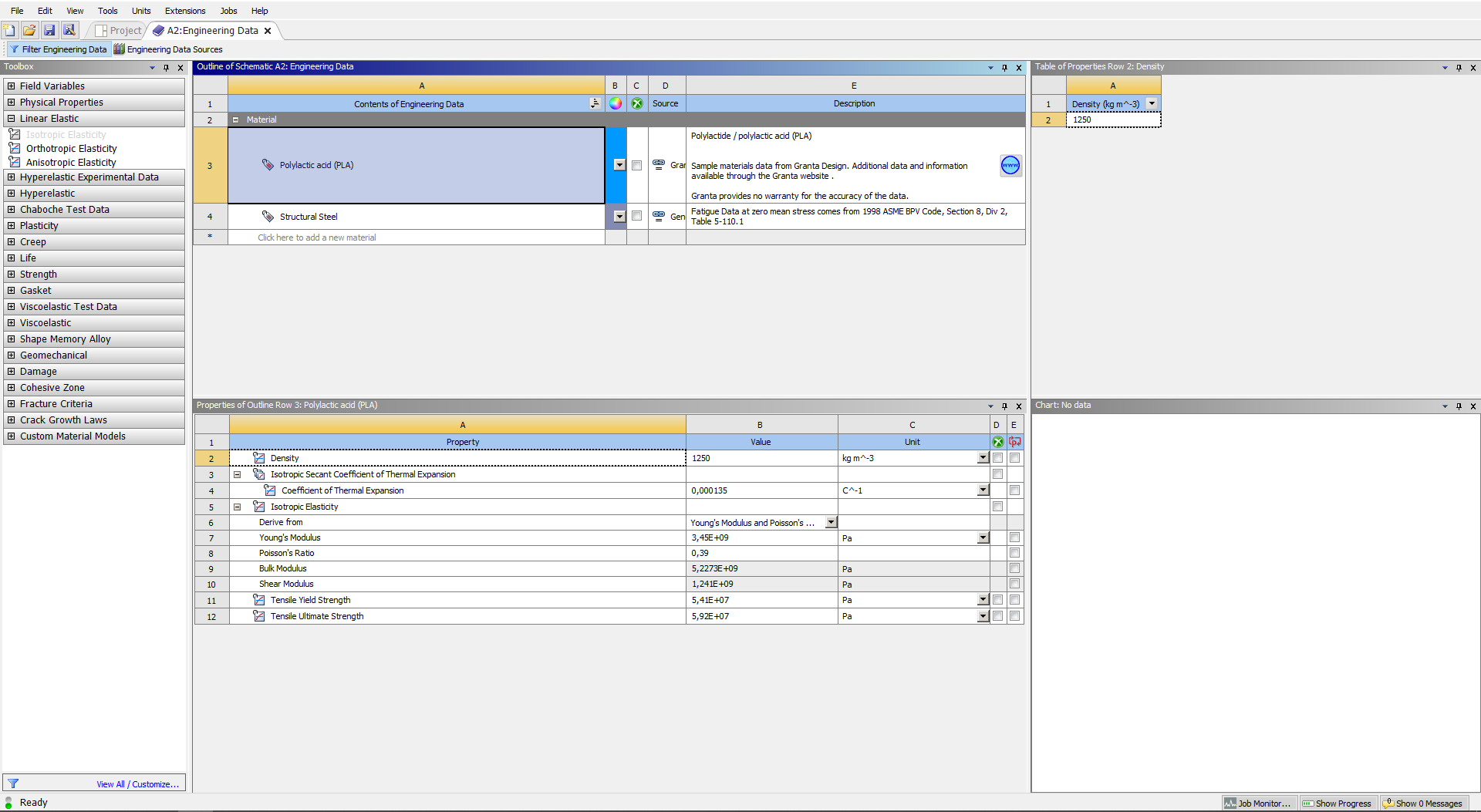 nI was supposed to study only the elastic range. But the displacement I'm applying even though is small (2[mm]) produces very high Stress values. These values are higher than the Tensile Yield Strenght (54,1 [MPa]). This means I'm not longer on the elastic range and that's why I'm getting this singularity??nWhy I'm getting a singularity?? Are the boundary conditions incorrect??nI'll try to slice the part since indeed is symmetric. Thank you for your help n
January 18, 2021 at 12:07 pmForum ModeratorGenerally, you will see singularities at sharp edges, Google Singularities FEA and check first few links for some more info!n-AniketnHow to access Ansys help linksnGuidelines for Posting on Ansys Learning ForumnViewing 5 reply threads
nI was supposed to study only the elastic range. But the displacement I'm applying even though is small (2[mm]) produces very high Stress values. These values are higher than the Tensile Yield Strenght (54,1 [MPa]). This means I'm not longer on the elastic range and that's why I'm getting this singularity??nWhy I'm getting a singularity?? Are the boundary conditions incorrect??nI'll try to slice the part since indeed is symmetric. Thank you for your help n
January 18, 2021 at 12:07 pmForum ModeratorGenerally, you will see singularities at sharp edges, Google Singularities FEA and check first few links for some more info!n-AniketnHow to access Ansys help linksnGuidelines for Posting on Ansys Learning ForumnViewing 5 reply threads- The topic ‘What are the boundary conditions that I must apply to perform a stress test on my part?’ is closed to new replies.
Innovation Space Trending discussions
 Top Contributors
-
peteroznewman
 6495
6495 -
scabo
 1906
1906 -
Dennis Chen
 1458
1458 -
javat33489
 1308
1308 -
Shyam Prasad V Atri
1022
Top Rated Tags
© 2026 Copyright ANSYS, Inc. All rights reserved.
Ansys does not support the usage of unauthorized Ansys software. Please visit www.ansys.com to obtain an official distribution.
-
Ansys Assistant will be unavailable on the Learning Forum starting January 30. An upgraded version is coming soon. We apologize for any inconvenience and appreciate your patience. Stay tuned for updates.