-
-
August 31, 2020 at 9:08 pm
vkr535
SubscriberHello Team,
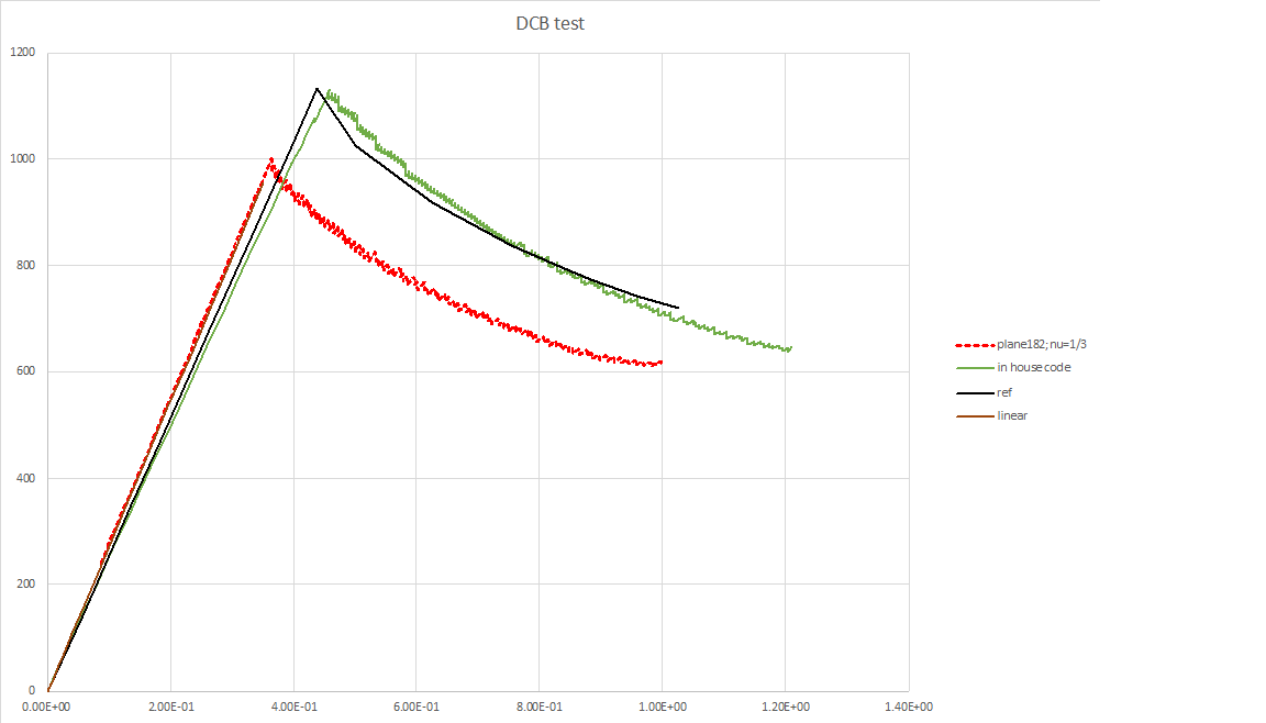
I faced an issue while validating the DCB test for delamination using Ansys plane 182 plane stress option using VCCT.
-->The critical load as predicted by ansys doesn't seem to match with the expected values: It under-predicts the critical load for delamination.
-->Also, the initial slope of the force-deflection before the failure initiates also appears to be not matching.
I tried refining the mesh and using higher order but the issue still persists.
I have attached the input file: dcb.dat to reproduce this issue. Also attached is the image of the various simulated results.
The parameters of DCB are:
L=200 !* length
dh=40 !* total thickness
a0=100 ! pre-crack length
nel=200 !* no.elements along length
neh=40 !* no.elements along thick
emod=2.0e+05 ! E
thick=10 ! width
g1c=0.9628 !* critical energy-release rate
pratio=0.3 ! *Proisson ratio
Please let me know your comments on observed results and suggestions. also, may i know if there is any validation problem to verify using plane stress option.
August 31, 2020 at 11:23 pmpeteroznewman
SubscriberWhere do the expected results come from?nYour plot legend says ref and in house code. What are those?nSeptember 1, 2020 at 12:18 amSubscriberHello,nRef is taken from the paper: Wei-Jian Li, Qi-Zhi Zhu, Tao Ni,nA local strain-based implementation strategy for the extended peridynamic model with bond rotation, Computer Methods in Applied Mechanics and Engineering,nVolume 358, 2020, 112625,ISSN 0045-7825, https://doi.org/10.1016/j.cma.2019.112625.(http:/www.sciencedirect.com/science/article/pii/S0045782519305079)nIn house codes are ones we are trying to reproduce and match with Ansys results. i'm unable to attach the input file, so copied those contents here:finishn/clear,nostartn/prep7 ndis1=0.35 ! >=0.397435 0.4 (1125.94)ndis2=1.0nn1=1000nn2=1000nn3=10ndl=200 !* lengthndh=40 !* total thicknessna0=100nnel=200 !* no.elements along lengthnneh=40 !* no.elements along thickntoler=0.1e-5nemod=2.0e+05nthick=10ng1c=0.9628 !* critical energy-release rateng2c=0.0ng3c=0.0nEI=emod*0.5*dh*0.5*dh*0.5*dh*thick/12ndeno=emod*0.5*dh*0.5*dh*0.5*dhnPc=sqrt(g1c*deno/3.0)*(thick/(2*a0))nUc=2*sqrt(g1c/(3*deno))*a0*a0npratio=0.4nnet,1,182 !* 2d 4-node structural solid elementn!keyopt,1,1,2 !* enhance strain formulationnkeyopt,1,3,3 !* plane strainnet,2,182n!keyopt,2,1,2nkeyopt,2,3,3nnet,3,202 !* 2d 4-node cohesive zone elementn!keyopt,3,2,2 !* element free optionnkeyopt,3,3,3 !* plane strainnnR,1,thicknmp,ex,1,emodnmp,prxy,1,prationtb,cgcr,1,,3,linear !* linear fracture criterionntbdata,1,g1c,g2c,g3cnn! fe modelnrectng,0,dl,0,dh/2 !* define areasnrectng,0,dl,0,-dh/2nlsel,s,line,,2,8,2 !* define line divisionnlesize,all,dh/nehnlsel,invenlesize,all, , ,nelnallsel,allntype,1 !* mesh area 2nmat,1nlocal,11,0,0,0,0nesys,11namesh,2ncsys,0ntype,2 !* mesh area 1nesys,11namesh,1nseltol,1e-06ncsys,0nnsel,s,loc,x,a0-toler,dlnnummrg,nodesneslnntype,3nmat,5nczmesh,,,1,y,0, !* generate interface elementsnallsel,allnnsel,s,loc,x,dl !* apply constraintsnd,all,allnnsel,allnn!nesel,s,ename,,202 !* select interface element toncm,cpath,elem !* define crack-growth pathnnnslennsel,s,loc,x,a0nnsel,r,loc,y,0neslnncm,crack1,node !* define crack-tip node componentnallselnfinishnn/solunresc,,nonenesel,s,type,,2nnsle,snnsel,r,loc,xnnsel,r,loc,y,dh/2 !* apply displacement loading on topnd,all,uy, dis1nnsel,allnesel,allnesel,s,type,,1nnsle,snnsel,r,loc,xnnsel,r,loc,y,-dh/2 !* apply displacement loading on bottomnd,all,uy,-dis1nnsel,allnesel,allnautots,onnnsubs,4,4,4ntime,1nncint,new,1 !* crack idncint,type,vcct !* vcct calculationncint,ctnc,crack1 !* crack-tip node componentncint,norm,0,2nn! crack-growth simulation setncgrow,new,1 !* crack-growth setncgrow,cid,1 !* cint id for vcct calculationncgrow,cpath,cpath !* crack pathncgrow,fcop,mtab,1 !* fracture criterionnCGROW,DTIME,2.0e-3nCGROW,DTMIN,2.0e-3nCGROW,DTMAX,2.0e-3ncgrow,fcra,1.02nnallsel,allnoutres,all,allnsolvenesel,s,type,,2nnsle,snnsel,r,loc,xnnsel,r,loc,y,dh/2 !* apply displacement loading on topnd,all,uy, dis2nnsel,allnesel,allnesel,s,type,,1nnsle,snnsel,r,loc,xnnsel,r,loc,y,-dh/2 !* apply displacement loading on bottomnd,all,uy,-dis2nnsel,allnesel,allntime,2nnsub,n1,n2,n3nsolvenfinishnn/post1nset,listn*GET,nmaxset, ACTIVE, 0, SET, NSETn*dim,imp_vol,,nmaxset,4,1n/com, *********************************n/com, Reference results:n/com, A local strain-based implementation strategy for the extended n/com, peridynamic model with bond rotation Comput. Methods Appl. Mech. Eng., 358 (2020), p. 112625n/com, *********************************nimp_vol(1,3,1)=0tnimp_vol(1,4,1)=0nimp_vol(2,3,1)=0.056544503tnimp_vol(2,4,1)=144nimp_vol(3,3,1)=0.136125654tnimp_vol(3,4,1)=350.7692308nimp_vol(4,3,1)=0.184293194tnimp_vol(4,4,1)=474.4615385nimp_vol(5,3,1)=0.262827225tnimp_vol(5,4,1)=679.3846154nimp_vol(6,3,1)=0.339267016tnimp_vol(6,4,1)=876.9230769nimp_vol(7,3,1)=0.396858639nimp_vol(7,4,1)=1026.461538nimp_vol(8,3,1)=0.436649215tnimp_vol(8,4,1)=1133.538462nimp_vol(9,3,1)=0.49947644tnimp_vol(9,4,1)=1028.307692nimp_vol(10,3,1)=0.62513089nimp_vol(10,4,1)=t919.3846154nimp_vol(11,3,1)=0.753926702nimp_vol(11,4,1)=t838.1538462nimp_vol(12,3,1)=0.823036649nimp_vol(12,4,1)=t803.0769231nimp_vol(13,3,1)=0.882722513tnimp_vol(13,4,1)=773.5384615nimp_vol(14,3,1)=0.956020942nimp_vol(14,4,1)=t744nimp_vol(15,3,1)=1.02408377nimp_vol(15,4,1)=t721.8461538n*cfopen,dcb_disp_force-ref,datn*vwrite,imp_vol(1,3,1), imp_vol(1,4,1)n(1x,2G20.") n*cfclosenfininn/post26nnsel,s,loc,y,dh/2nnsel,r,loc,x,0n*get,ntop,node,0,num,maxnnsel,allnnsol,2,ntop,u,y,uynrforce,3,ntop,f,y,fynprod,5,2, , ,dis_tip, , ,1.0nprod,6,3, , ,rf , , ,1.0nxvar,5n/title,, dcb: reaction at top node verses prescribed displacementn/axlab,x,disp Uy (mm)n/axlab,y,reaction force Fy (N)nplvar,6n/com, export data to array parametersnvget,imp_vol(1,1,1),5nvget,imp_vol(1,2,1),6n*cfopen,dcb_disp_force,datn*vwrite,imp_vol(1,1,1), imp_vol(1,2,1)n(1x,4G20.n*cfclosenfinish
Viewing 2 reply threads
n*cfclosenfininn/post26nnsel,s,loc,y,dh/2nnsel,r,loc,x,0n*get,ntop,node,0,num,maxnnsel,allnnsol,2,ntop,u,y,uynrforce,3,ntop,f,y,fynprod,5,2, , ,dis_tip, , ,1.0nprod,6,3, , ,rf , , ,1.0nxvar,5n/title,, dcb: reaction at top node verses prescribed displacementn/axlab,x,disp Uy (mm)n/axlab,y,reaction force Fy (N)nplvar,6n/com, export data to array parametersnvget,imp_vol(1,1,1),5nvget,imp_vol(1,2,1),6n*cfopen,dcb_disp_force,datn*vwrite,imp_vol(1,1,1), imp_vol(1,2,1)n(1x,4G20.n*cfclosenfinish
Viewing 2 reply threads- The topic ‘VCCT delamination using plane182 with plane stress with thickness’ is closed to new replies.
Innovation Space Trending discussions
 Top Contributors
-
peteroznewman
 6495
6495 -
scabo
 1906
1906 -
Dennis Chen
 1458
1458 -
javat33489
 1308
1308 -
Shyam Prasad V Atri
1022
Top Rated Tags
© 2026 Copyright ANSYS, Inc. All rights reserved.
Ansys does not support the usage of unauthorized Ansys software. Please visit www.ansys.com to obtain an official distribution.
-
Ansys Assistant will be unavailable on the Learning Forum starting January 30. An upgraded version is coming soon. We apologize for any inconvenience and appreciate your patience. Stay tuned for updates.