
-
-
December 11, 2020 at 5:03 pm
yappyap
SubscriberHi all,
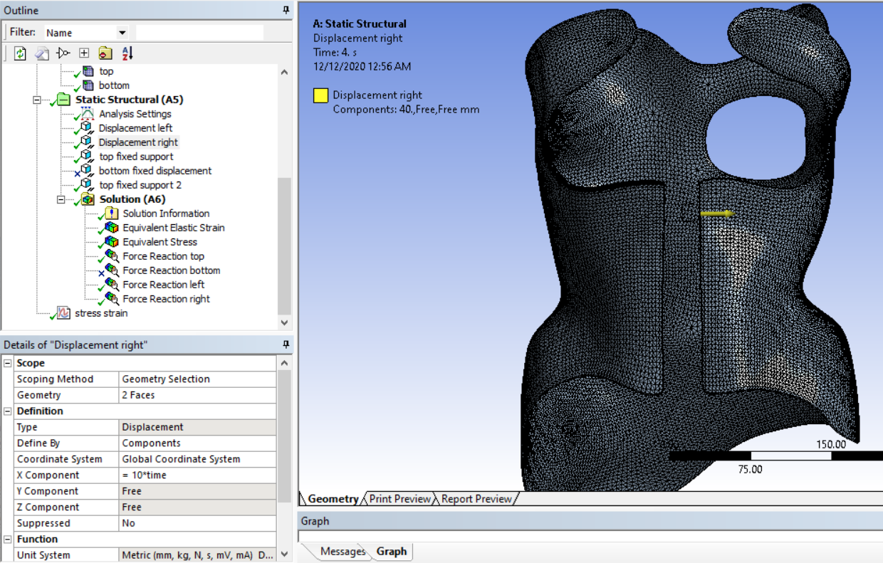
I've been trying to obtain a bilinear stress-strain curve on my brace (the model) which experiences a displacement in front to open the brace up.
Displacement on the left and right:
December 12, 2020 at 12:51 pmpeteroznewman
SubscribernA stress-strain curve is an input to the material model. It's not that useful to plot in the model. What is important to plot is the force to open the brace and the amount of plastic strain that develops in the material at the maximum opening of the brace.nThe problem you have is that you are using solid elements that wrap around most of a circle. When you use an orthotropic material, the properties are aligned to the global coordinate axis directions. How are you making the properties align with the thickness direction of the brace from the front to the side to the back?nI recommend you go back an isotropic material. The orthotropic modulus does not vary by a large amount. For example, there is only a 5% variation from the largest to the smallest value of Young's Modulus in the different axis directions. Take the average of the three values and use that in an isotropic material model.nI also recommend you go back to CAD and extract a surface model of this brace and assign the thickness in Mechanical. The shell elements include layers that can keep track of plasticity through the thickness of the element.nComposite materials that are a layup of fibers at different angles bonded into an epoxy resin can be simulated accurately in ANSYS. The ACP/Pre and ACP/Post components allow the analyst to define an orthotropic material using the actual properties of the fibers in the composite layup.nDecember 12, 2020 at 2:33 pmSubscribernThank you so much for your suggestions; I really appreciate it!nI have thought of extracting a surface model but my current CAD design has triangulations as the model is obtained from a 3D scanner. Are there any other methods to use shell elements?nThank you once again.nDecember 12, 2020 at 4:01 pmSubscribernIt would be tedious, but if you open the CAD model in SpaceClaim, you can convert the solid to a Facet Body. Then on the Tools tab of SpaceClaim, you can create surface geometry using the Skin Surface tool until you have covered one side of the brace.nDecember 12, 2020 at 5:58 pmSubscribernnI tried it but i can't seem to click on the green tick?n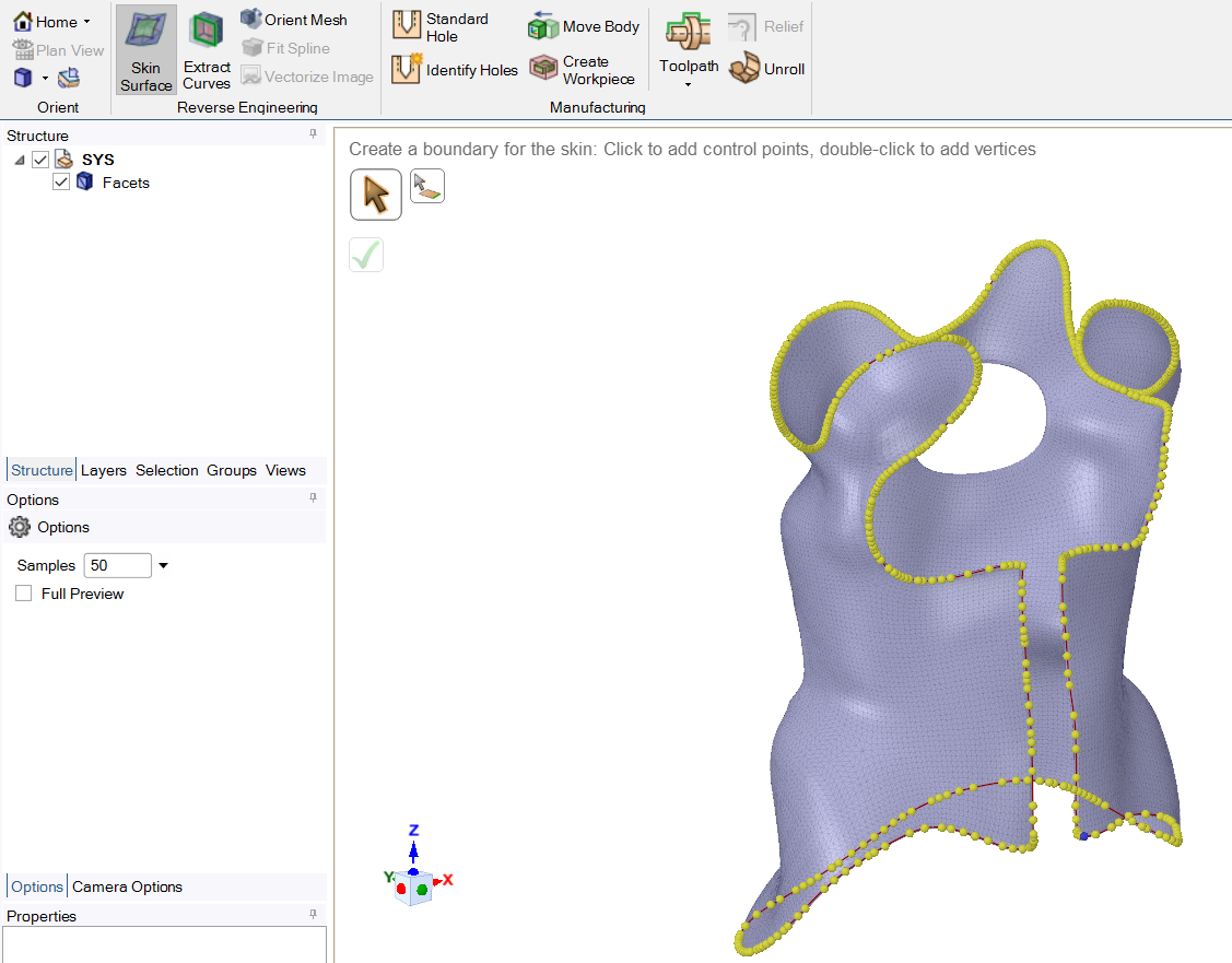 I then tried to trace another boundary (the hole) but there was an error:n
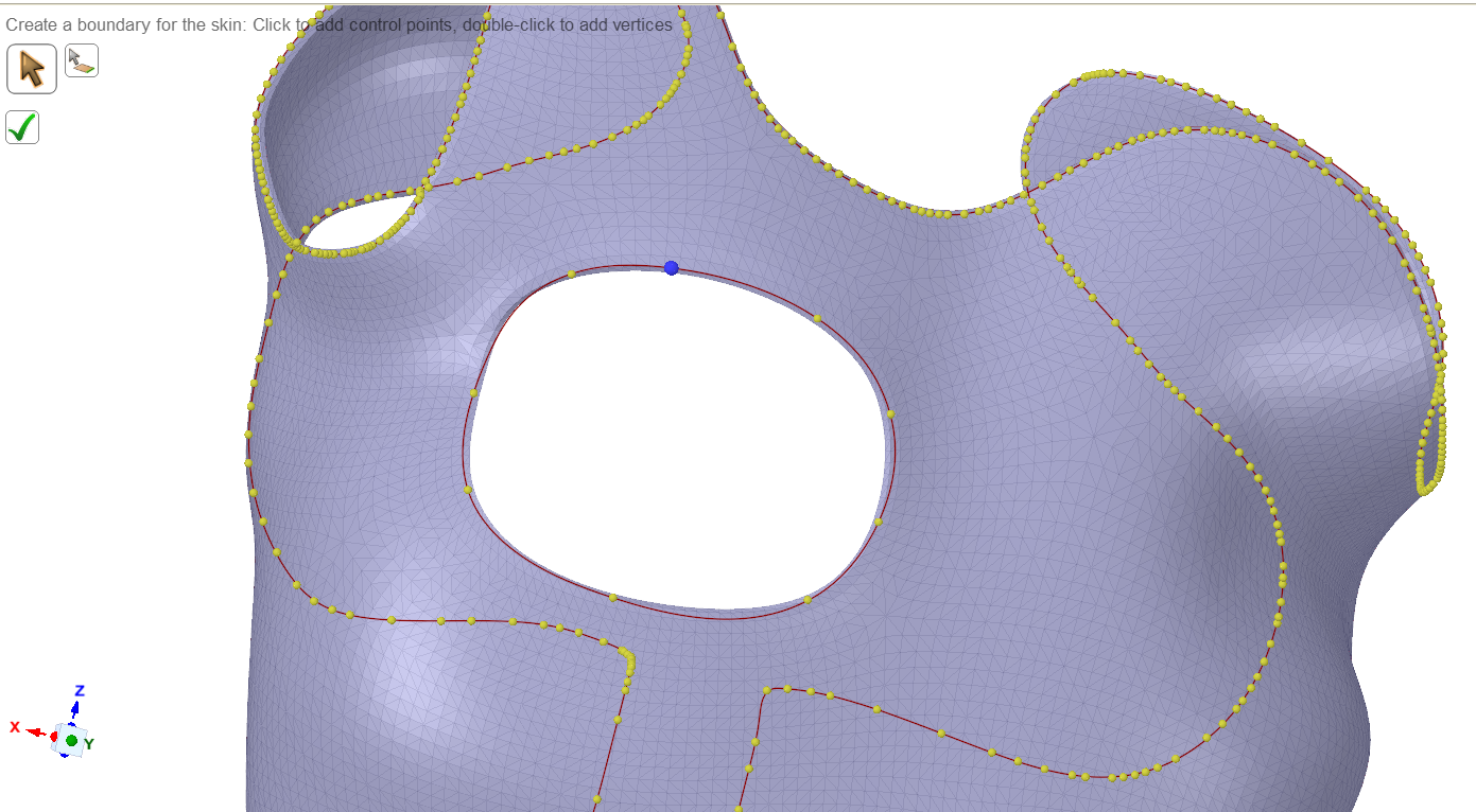
 nAm I doing it wrong?n
December 12, 2020 at 6:13 pmSubscribernDon't try to get the whole brace done in one go.nYou can use planes to slice the solid body into smaller pieces, then try to skin one side of each piece.nThe individual skins can later be united into a single part in SpaceClaim, or left separate and joined by Shared Topology.nI can't promise anything, but if you attach a zip file containing the STL file, I might give it a try. nDecember 12, 2020 at 6:33 pmSubscribernI have attached the zip file! I will try your suggestions too.nThank you!nDecember 12, 2020 at 6:44 pmSubscribernOkay, thanks. Please reply with the version of ANSYS you are using.nDecember 12, 2020 at 7:22 pmSubscriberI am using 19.2 nDecember 13, 2020 at 4:04 amSubscriberDecember 13, 2020 at 5:55 amSubscriberThank you so much !!!!!nI'll give it a go.nMay I ask what is in the document attached? I unzipped it and couldn't open anything from SpaceClaim.n
nAm I doing it wrong?n
December 12, 2020 at 6:13 pmSubscribernDon't try to get the whole brace done in one go.nYou can use planes to slice the solid body into smaller pieces, then try to skin one side of each piece.nThe individual skins can later be united into a single part in SpaceClaim, or left separate and joined by Shared Topology.nI can't promise anything, but if you attach a zip file containing the STL file, I might give it a try. nDecember 12, 2020 at 6:33 pmSubscribernI have attached the zip file! I will try your suggestions too.nThank you!nDecember 12, 2020 at 6:44 pmSubscribernOkay, thanks. Please reply with the version of ANSYS you are using.nDecember 12, 2020 at 7:22 pmSubscriberI am using 19.2 nDecember 13, 2020 at 4:04 amSubscriberDecember 13, 2020 at 5:55 amSubscriberThank you so much !!!!!nI'll give it a go.nMay I ask what is in the document attached? I unzipped it and couldn't open anything from SpaceClaim.n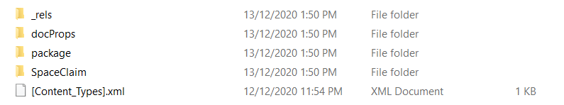 n
December 13, 2020 at 1:41 pmSubscribernA SpaceClaim 19.2 document file.n
n
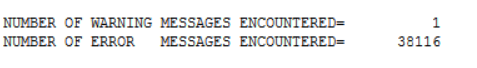
December 13, 2020 at 1:41 pmSubscribernA SpaceClaim 19.2 document file.n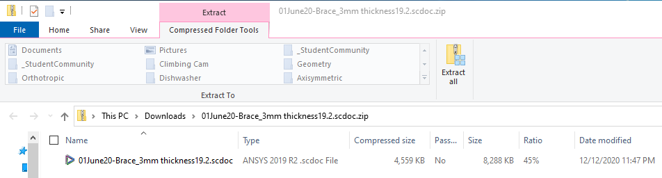 December 13, 2020 at 1:43 pmSubscriberI managed to turn the brace from solid to surface. nThank you so much for your guidance! nDecember 13, 2020 at 2:17 pmSubscriberHi Array, regarding shell elements, do i type this line ET, 1, SHELLXX into the Commands under Geometry? This is my first time working with commands in Mechanical so I'm quite unsure.nI am currently trying SHELL93 for my model but with that command line, i received an error Real constant set 1 undefined but referenced by element X where x is element number.n
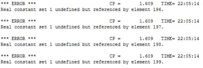
 n
December 13, 2020 at 3:36 pmSubscribernYou don't need any commands under Geometry to use shell elements. All you need to do under geometry is pick the surface(s) and assign a material and a thickness of 3 mm.nWhen you mesh and solve, a suitable element type will automatically be assigned. You can see what element was assigned in the solution output.nDecember 13, 2020 at 4:31 pmSubscribernIf I would like to change the element type to compare element quality, how do I do so?nDecember 13, 2020 at 5:07 pmSubscribernSHELL181 is the linear shell element and 281 is the quadratic shell element for structural problems.nThe mesh is either linear or quadratic and you can control which one it is and the correct element will automatically be assigned. You will get an error if you try to assign a linear element type to a quadratic mesh and vice versa.nElement quality generally refers to the shape of the element. You can plot element quality using the mesh metrics capability.nOne reason to change element type is if you are solving a thermal model. But if you use Workbench, you simply pull over a Thermal analysis, link the models, which will copy the mesh, and when you solve, the element type will automatically become a SHELL131 or 132 which has temperature DOF instead of displacement DOF.nSHELL93 is not in the list of elements in the 19.2 ANSYS Help Element Library. If you want to change the element type, use the following code under the body:net,matid,enamenwhere matid automatically looks up the material for that body and ename is shell181 or any valid element type that has the correct number of nodes for the mesh you have.nDecember 13, 2020 at 6:46 pmSubscriberThank you !nDecember 13, 2020 at 6:49 pmSubscriberOne last question please, nWhy does my stress-strain curve have a vertical line even though I did input tangent modulus to be 0?n
n
December 13, 2020 at 3:36 pmSubscribernYou don't need any commands under Geometry to use shell elements. All you need to do under geometry is pick the surface(s) and assign a material and a thickness of 3 mm.nWhen you mesh and solve, a suitable element type will automatically be assigned. You can see what element was assigned in the solution output.nDecember 13, 2020 at 4:31 pmSubscribernIf I would like to change the element type to compare element quality, how do I do so?nDecember 13, 2020 at 5:07 pmSubscribernSHELL181 is the linear shell element and 281 is the quadratic shell element for structural problems.nThe mesh is either linear or quadratic and you can control which one it is and the correct element will automatically be assigned. You will get an error if you try to assign a linear element type to a quadratic mesh and vice versa.nElement quality generally refers to the shape of the element. You can plot element quality using the mesh metrics capability.nOne reason to change element type is if you are solving a thermal model. But if you use Workbench, you simply pull over a Thermal analysis, link the models, which will copy the mesh, and when you solve, the element type will automatically become a SHELL131 or 132 which has temperature DOF instead of displacement DOF.nSHELL93 is not in the list of elements in the 19.2 ANSYS Help Element Library. If you want to change the element type, use the following code under the body:net,matid,enamenwhere matid automatically looks up the material for that body and ename is shell181 or any valid element type that has the correct number of nodes for the mesh you have.nDecember 13, 2020 at 6:46 pmSubscriberThank you !nDecember 13, 2020 at 6:49 pmSubscriberOne last question please, nWhy does my stress-strain curve have a vertical line even though I did input tangent modulus to be 0?n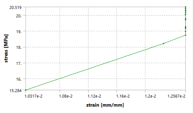 n
December 13, 2020 at 11:53 pmSubscribernI recommend you build a much simpler model, a simple square block with 3 planes of symmetry, meshed with a single linear element. Pull on one face with a displacement and you can output the exact curve you input into the material model. It seems important for you to see the input you used in the material model show up as an output, so do this to build some confidence. I did that in the discussion link below.n/forum/discussion/1115/stress-strain-diagramnAfter that experience, with a good amount of work, we could figure out why you get the plot above if you still want to know.nJanuary 1, 2021 at 6:18 pmSubscribernViewing 20 reply threads
n
December 13, 2020 at 11:53 pmSubscribernI recommend you build a much simpler model, a simple square block with 3 planes of symmetry, meshed with a single linear element. Pull on one face with a displacement and you can output the exact curve you input into the material model. It seems important for you to see the input you used in the material model show up as an output, so do this to build some confidence. I did that in the discussion link below.n/forum/discussion/1115/stress-strain-diagramnAfter that experience, with a good amount of work, we could figure out why you get the plot above if you still want to know.nJanuary 1, 2021 at 6:18 pmSubscribernViewing 20 reply threads- The topic ‘stress-strain curve not bilinear’ is closed to new replies.
Innovation Space Trending discussions
 Top Contributors
-
peteroznewman
 6495
6495 -
scabo
 1906
1906 -
Dennis Chen
 1458
1458 -
javat33489
 1308
1308 -
Shyam Prasad V Atri
1022
Top Rated Tags
© 2026 Copyright ANSYS, Inc. All rights reserved.
Ansys does not support the usage of unauthorized Ansys software. Please visit www.ansys.com to obtain an official distribution.
-


The Ansys Learning Forum is a public forum. You are prohibited from providing (i) information that is confidential to You, your employer, or any third party, (ii) Personal Data or individually identifiable health information, (iii) any information that is U.S. Government Classified, Controlled Unclassified Information, International Traffic in Arms Regulators (ITAR) or Export Administration Regulators (EAR) controlled or otherwise have been determined by the United States Government or by a foreign government to require protection against unauthorized disclosure for reasons of national security, or (iv) topics or information restricted by the People's Republic of China data protection and privacy laws.
