-
-
March 8, 2019 at 6:55 am
btingthewind
Subscriberhi
dear you,
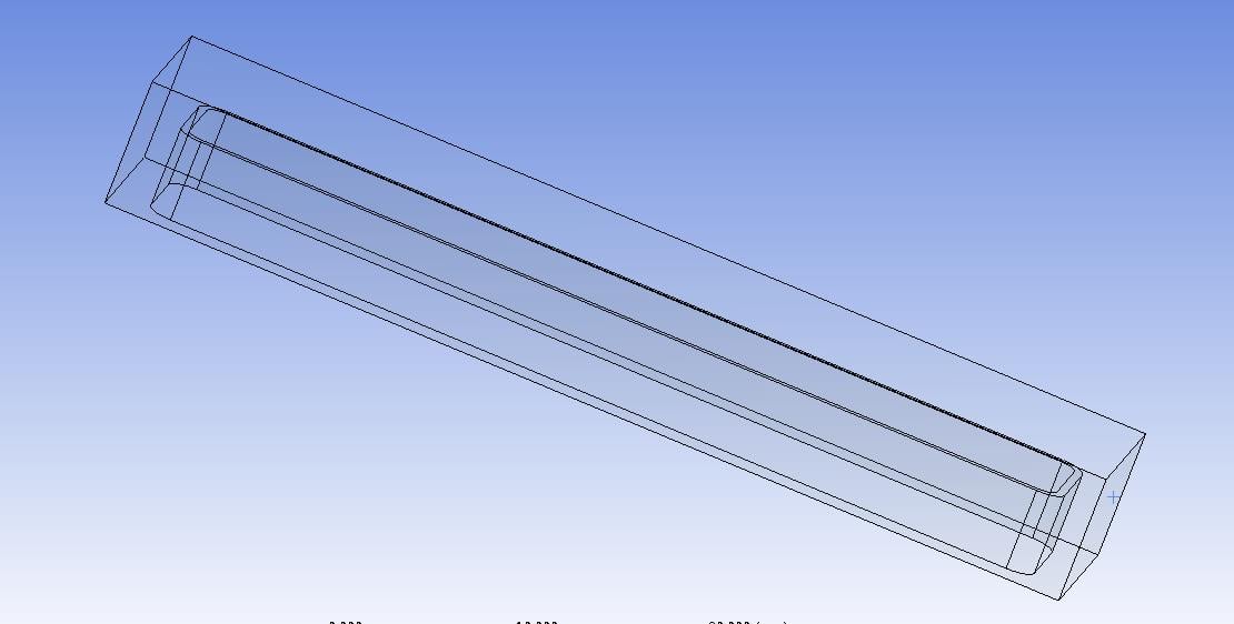
sorry for bothering, recently i am working on a geom, which has sharp corners, as the pic attached below:
then i need to generate inflation layers on the three selected faces for CFD usage, as showed in the following pic,the first layer thickness is 0.3297mm, growth rate=1.2, layer numbers=3,
the meshing method is patch conforming,as a consequent, there comes low quality element, its max skewness=0.91,
obviously ,the mesh quality is not CFD computation. Then I do many trials to decrease the max skewness, by changing the global/local default meshing parameters, mesh method, etc. but it does not work to the geom, the max skewness still cannot go down.
Can someone help me?
THANKS
BEST REGARDS
-
March 8, 2019 at 10:26 am
Rob
Forum ModeratorNow you've located the poor cells (I'd run with 0.91 skew in Fluent) put a section through the model (show full cells). Check the sizing on the opposing faces and how the mesh between the inflation is behaving: chances are you've got a narrow gap between inflation or some other setting that's causing a conflict.
-
March 10, 2019 at 2:13 am
btingthewind
Subscriberthank you sir,
i tried lots, but it still does not work, the skewness is still that high.
Could I email the geom to you?
Sorry for bothering you
BEST REGARDS
-
March 10, 2019 at 3:24 am
peteroznewman
SubscriberCreate a Workbench Project Archive .wbpz file and attach it to your previous post. I will reply with mesh suggestions.
-
March 10, 2019 at 4:41 am
btingthewind
SubscriberThank you sir,
I've tried to change the inflation options (i.e. smooth transition, total thickness, first layer thickness, changing the layer height, growth rate, etc). Also I've modified the mesh sizing options (global mesh) - i.e. advanced size function, relevance center, smoothing, min-max size, growth rate, etc.
but it does work, then i try to slice the gap from the geom to multizone mesh method, this works in the sliced gap body, the skewness can decrease to 0.7 , however, skewness of cells adjacent to the sliced gap body still keeps 0.9.
now i really don't know how to solve the problem.
thanks for your response.
BEST REGARDS
-
March 10, 2019 at 6:36 am
peteroznewman
SubscriberHere is the mesh quality of the archive provided.
I made some geometry changes and some mesh control changes. If you just Generate Mesh and let the mesher decide which body to mesh first, you get this quality...
But if you Generate Mesh on Selected Body on the tube part first, and then finish with Generate Mesh, you get a better quality.
-
March 15, 2019 at 12:27 pm
btingthewind
SubscriberThank you ,sir
-
March 15, 2019 at 12:39 pm
btingthewind
Subscriberthank you, sir.
I have tried the method you provided, but it does not work well, a way to improve the mesh quality of my geom is having no inflation layers in the gaps, by doing so , the max skewness can decrease to 0.89.
another question puzzling me is ,when we generate mesh in ANSYS MESHING, should we care about the averaged skewness or the max value?
BEST REGARDS
-
March 15, 2019 at 1:46 pm
peteroznewman
SubscriberYou should worry about the maximum skewed element. Extremely skewed elements can cause the entire simulation to calculate wrong solutions. Maybe a CFD expert will add to this comment.
If the gaps have no significant velocity, then you can leave out the inflation layer at those walls, but if there is a significant velocity, then it might be better to have high skew elements to capture the velocity gradient, than low skew elements that fail to capture the velocity gradient from the wall. Maybe a CFD expert will add a comment.
-
- The topic ‘how to improve the inflation quality at sharp corners?’ is closed to new replies.


-
3044
-
971
-
884
-
858
-
792

© 2025 Copyright ANSYS, Inc. All rights reserved.


