Ansys Assistant will be unavailable on the Learning Forum starting January 30. An upgraded version is coming soon. We apologize for any inconvenience and appreciate your patience. Stay tuned for updates.
General Mechanical

General Mechanical

Topics related to Mechanical Enterprise, Motion, Additive Print and more.

How do I set the COMBIN39-element as a 2D-longitudinal spring to model a shear connection?

    • DinuL
      Subscriber

      Hi,

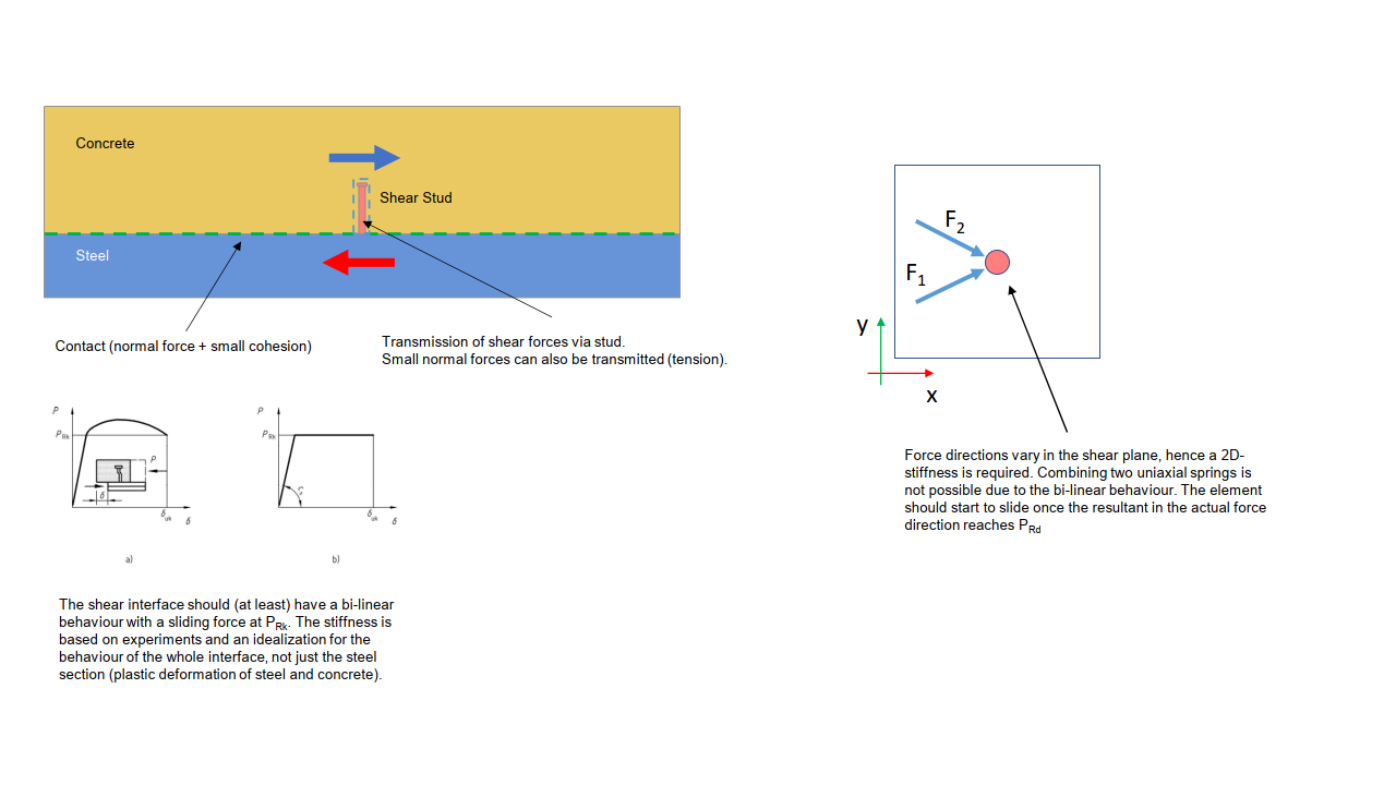
      I'm trying to model a concrete-steel composite structure. The interface / shear connection between concrete and steel is realized through shear studs, which should be represented as spring elements in my analysis. The idea is to use the COMBIN39 element with KEYOPT(4) set to 3 (2D-longitudinal spring). I chose the 2D option because I will most likely have forces acting in various directions in the interface-plane and thus need an element that is able to capture the "resulting" force (instead of having two separate springs in x- and y-direction of the base plane). This is especially important since the springs will have a sliding force that also should refer to the resulting force.

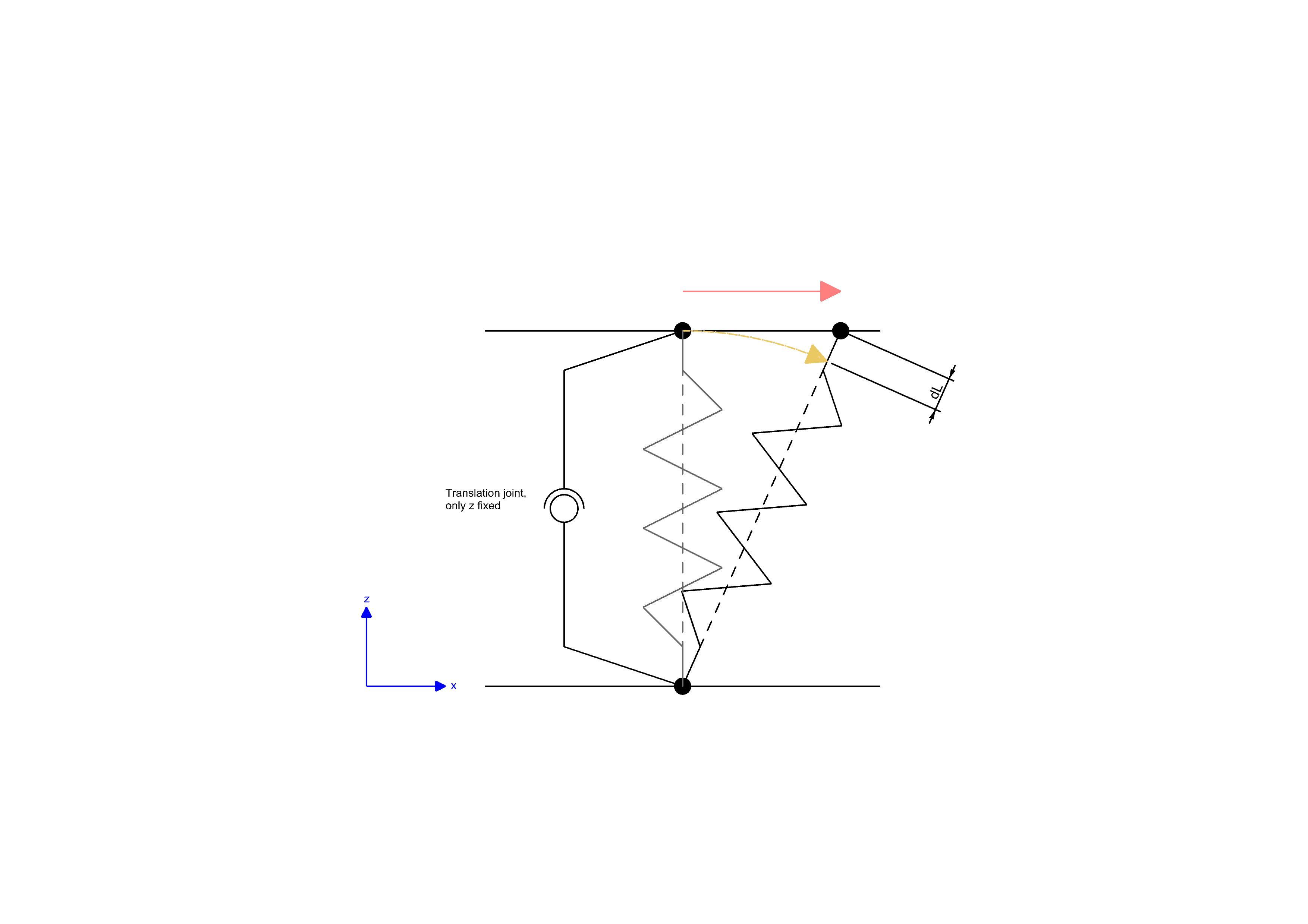
      I did a simple test model in Mechanical and managed to manually change my spring connections to COMBIN39 and setting the relevant KEYOPTs. Springs also work fine in the main direction (connection line between the nodes, aligned with global x) but I don't get them to work in the transversal direction (global y in my case), there seems to be no stiffness activated when I apply the loads.

      The COMBIN30 description states that for the 2D-longitudinal element, the "element must lie in an X-Y plane". Is that referred to an element coordinate system, or does this special option require a global X-Y plane / 2D-analysis?

      Any thoughts/ideas on that would be highly appreciated.

    • Sheldon Imaoka
      Ansys Employee

      Is your analysis 3D or 2D in nature? KEYOPT(4)=3 for COMBIN39 is intended for a 2D analysis where the elements only lie on the z=0 XY plane.
      Is it that you don't want any resistance in the Z direction, so is that why you only want the spring to work in X and Y directions? Do you also need a nonlinear spring? Also, are the nodes coincident?
      If you just want linear stiffness behavior only for X & Y but not Z, an option may be COMBI214 - it is intended for modeling bearings, but you may be able to utilize it for your application.
      Regards Sheldon
    • DinuL
      Subscriber

      thanks for your reply!
      My analysis is 3D in nature, which explains the issues I had setting up the element correctly. The nodes could be coincident or with an offset, I can still adjust the model to my needs. A 3D-Element with a very small stiffness in z-direction could also work. I made some sketches to explain the problem, if you wouldn't mind having a look. As shown there things get complicated (at least for me) with the changing load directions and the bi-linear behavior which makes it difficult to operate with longitudinal elements.
      If there is a possibility to model this with springs, I'd be very happy, since the actual problem I'm solving is rather big and has lots of those connections (~2000).

    • Sheldon Imaoka
      Ansys Employee

      Thanks for the detailed information about your application. The situation you describe is an interesting one. Unfortunately, I'm at a loss at how best to model this in a simplified manner.
      Since you already have contact elements there, one thought was to duplicate the contact at the stud location (create a duplicate contact pair, but contact side only has 1 element at each stud location) and use CZM (cohesive zone model). You can define a shear traction-separation behavior. The drawbacks are that (a) traction-separation is not exactly the same as the bilinear behavior you want, although it can still capture when 'failure' (reaching P_Rk) is reached since you lose stiffness at that point, and (b) there will be very high stiffness in normal direction rather than little/no stiffness. So if the concrete and steel are expected to separate, this approach won't work, but if the two materials are assumed to be compressed together will little/no chance of separation, CZM may work.
      Unfortunately, I can't think of a simple/elegant solution to this with a spring-like element. Other options, like embedding a short BEAM element with plasticity and connecting both ends of the beam to the surrounding material (concrete one side, steel on the other) may be needed, but that takes a lot of effort since you can't just share a BEAM node with a SOLID node because the solid elements don't have rotational DOF, so they don't transfer moments directly. This could be circumvented a bit by making the beam a little 'deep' inside both materials and sharing more than just 1 node for each material side.
      Regards Sheldon

    • DinuL
      Subscriber

      thanks for taking the time to think about my problem. I'll have a look at the CZM, ideally steel and concrete should not separate, so maybe that is an option.
      Another idea I came up with is using a 3D-Combin39 spring (KEYOPT(4),1) that connects the steel and concrete parts in combination with a joint that couples the vertical movements of the spring end points. The spring element behaves as some sort of pendulum in that approach. The length "dL" of the spring can be calculated for a given horizontal displacement so that the load-deflection curve can be adjusted to match my actual bi-linear behavior. I haven't thought it through to the end, but maybe this might be a reasonably simple solution to the problem.


Viewing 4 reply threads
  • The topic ‘How do I set the COMBIN39-element as a 2D-longitudinal spring to model a shear connection?’ is closed to new replies.
[bingo_chatbox]