TAGGED: shear
-
-
September 16, 2025 at 10:22 am
UNI
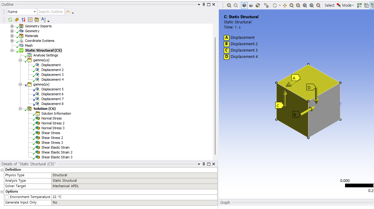
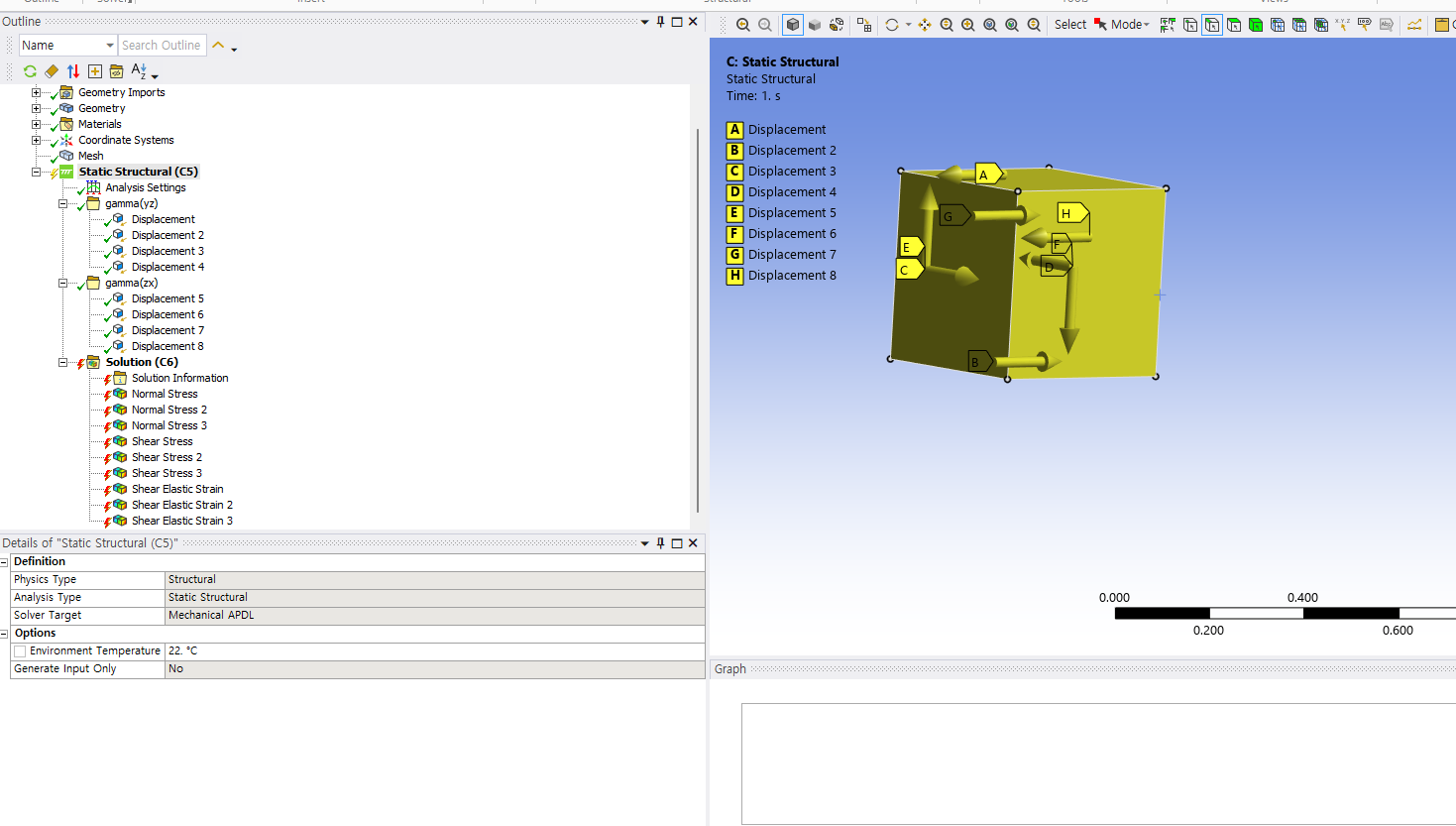
SubscriberIt was relatively straightforward to impose a shear strain of 0.001 in the YZ component. As shown in the figure, I simply applied uniform displacements on the four faces. However, when I attempted to impose shear strain in the ZX component through displacements, an error occurred because the faces where the YZ displacements had been applied share a common edge. How can I resolve this issue?
-
September 17, 2025 at 6:04 am
UNI
SubscriberThe issue has been resolved. When only the YZ component was present, I used Displacement. For the YZ & ZX case, I used both Displacement and Remote Displacement, and for the YZ, ZX & XY case, I used only Remote Displacement.
-
Viewing 1 reply thread
- You must be logged in to reply to this topic.
Ansys Innovation Space


Trending discussions


- The legend values are not changing.
- LPBF Simulation of dissimilar materials in ANSYS mechanical (Thermal Transient)
- Convergence error in modal analysis
- APDL, memory, solid
- How to model a bimodular material in Mechanical
- Meaning of the error
- Simulate a fan on the end of shaft
- Nonlinear load cases combinations
- Real Life Example of a non-symmetric eigenvalue problem
- How can the results of Pressures and Motions for all elements be obtained?
Top Contributors


-
3882
-
1414
-
1241
-
1118
-
1015
Top Rated Tags


© 2025 Copyright ANSYS, Inc. All rights reserved.
Ansys does not support the usage of unauthorized Ansys software. Please visit www.ansys.com to obtain an official distribution.


