-
-
December 11, 2020 at 10:24 pm
aimeri42
SubscriberDear community,
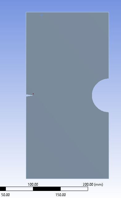
I am analyzing a 2D modified single edge notched tension specimen for different a/W ratios. The geometry is shown in Figure 1. (The experimental study is done by Kirk and Sanford).
The material is polypropylene (PP). For the elastic perfectly plastic model, Bilinear Kinematic Hardening was used with Tangent Modulus of 0. Could you please check and see if there is any mistake in the material data. The material data is shown in Figure 2.
The fracture is modelled using Pre-Mesh Cracked.
My goal is to find the plastic zone shape and size and compare it with Irwin' plastic zone.
For the shape I am using isolines (shown in Figure 3 - equivalent elastic strain) but how could I determine which one is the plastic zone and how do I extract/know the length of plastic zone?
Sincerely,
aimeri42
December 12, 2020 at 12:32 pmpeteroznewman
SubscribernYou can plot Equivalent Plastic Stain. The value is zero when the material is in the elastic range and above zero when the material has become plastic, so the 0 isoline is the zone of plasticity.nDecember 13, 2020 at 10:34 pmSubscriberEquivalent Plastic Strain is showing zero for the whole surface for most of the cases, which does not seem logical. If stress intensity factor is 360 MPa sqrt(mm), and Yield strength is 500 Mpa, the plastic zone radius is rp=1/2pi (Ki/Sy)^2 = 0.08mm, while it is showing zero in the equivalent plastic strain. nDo you have any idea why this is happening?nDecember 14, 2020 at 12:10 amSubscribernIt could be due to the element size. If the plastic zone radius is 0.08 mm, but the element size is larger than that, then the Gauss points inside the element are still in the elastic zone, even though a corner of the element is in the plastic zone. You need elements smaller than 0.08 mm to have them become plastic.nWhat is the element size around the crack tip?nDecember 14, 2020 at 7:09 pmSubscriberI was using elements of size of 1 mm around the crack tip. I changed them to 0.5 mm (vertex sizing, radius 15 mm). There is still no equivalent plastic strain. It was giving me large deflection warning, turned the large deflection mode on, but still the same. nI think the reason why this is happening is because the plastic zone radius is much smaller than the structure, hence it is controlled by elastic strain. What do you think? nDecember 14, 2020 at 9:22 pmSubscribernYou need elements smaller than 0.08 mm around the crack tip to have them become plastic.nDecember 14, 2020 at 11:21 pmSubscribernOh. A misread, sorry. Now the element size is 0.07mm. I created a named selection on the node as shown in the figure. I add the pre-crack on the named selection. However, the solution seems to not converge and gives me the following errors: nWhat could be the reason, or how I could fix it?.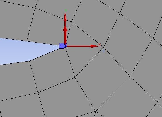 Figure 1. Node pre crackn
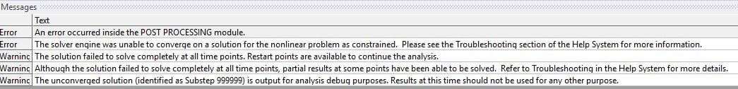 n
December 15, 2020 at 12:28 amSubscriberArraynLook at the posts in the Google search of this site for the term unable to converge. There are many standard methods to resolve this situation.nhttps://www.google.com/search?q=site%3Aforum.ansys.com+%22unable+to+converge%22nViewing 7 reply threads
n
December 15, 2020 at 12:28 amSubscriberArraynLook at the posts in the Google search of this site for the term unable to converge. There are many standard methods to resolve this situation.nhttps://www.google.com/search?q=site%3Aforum.ansys.com+%22unable+to+converge%22nViewing 7 reply threads- The topic ‘Elastic Perfectly Plastic – Plastic Zone Size and Shape – 2D Modified Single Edge Notched Tension’ is closed to new replies.
Innovation Space Trending discussions
 Top Contributors
-
peteroznewman
 6495
6495 -
scabo
 1906
1906 -
Dennis Chen
 1458
1458 -
javat33489
 1308
1308 -
Shyam Prasad V Atri
1022
Top Rated Tags
© 2026 Copyright ANSYS, Inc. All rights reserved.
Ansys does not support the usage of unauthorized Ansys software. Please visit www.ansys.com to obtain an official distribution.
-
Ansys Assistant will be unavailable on the Learning Forum starting January 30. An upgraded version is coming soon. We apologize for any inconvenience and appreciate your patience. Stay tuned for updates.