

-
-
January 4, 2021 at 11:19 am
smalbro93
SubscriberHi everyone,
Firstly, a happy new year to you all.
I am carrying out a simulation and my Cd values are lower than expected. I am looking for some help. Thank you.
Simulation Details:
Square cylinder (depth = 0.1m) inside a Circular Domain (Dia = 6m).
I am attaching the simulation results.
1) After around 4000 iterations, the solution diverges (residuals fluctuate in a wider range).
2) I am not sure why the Cd value is low. Re for the simulation is around 13000 and the Cd should be around 2.1, I get a value of around ~1.5. Do I need to use the Non-iterative Time Advancement?
Any help is appreciated. Thank you.
January 4, 2021 at 12:45 pmKeyur Kanade
Ansys EmployeeReference values are used to calculate Cd. nPlease check your reference values. Please go through help manual for more details nPlease check this forum which has lot of posts about Cd. nRegards,nKeyurnHow to access Ansys Online Help DocumentnHow to show full resolution imagenGuidelines on the Student CommunitynHow to use Google to search within Ansys Student CommunitynJanuary 4, 2021 at 2:47 pmSubscriberThank you for your response.nI have already checked the reference part. I have modified the Area parameter to 0.1 (square cylinder depth (it is a 2D simulation)), the inlet velocity, and the dynamic viscosity parameter as I had defined to match the Re I wanted. I am a little stuck here so I want to get some insights. Thank you. nThe simulation yields the correct answer in the case of a rectangular domain but the answers are weird when I use this circular domain. I am not sure why.nJanuary 4, 2021 at 3:51 pmRob
Forum ModeratorWhat inlet condition are you using for the circular domain? Specifically, how are you defining the velocity?nJanuary 5, 2021 at 3:55 amSubscribernHappy New Year to you.nThis is the 2D mesh; Blue Line shows the Inlet and Red shows the Outlet. First Cell Height = D/10 = 0.01 m (D = Cylinder depth = 0.1 m)n Inlet Boundary Conditions:nWind velocity of 1 m/s in the X-direction is defined as shown in the image.nTurbulent Boundary conditions: nTurbulent Energy: k = (3/2)*(inlet velocity* Turbulence Intensity)^2nSpecific Dissipation Rate: w = K^(1/2) / {0.09^(1/4)*Turbulence length scale}nI am taking the Turbulence Length Scale as 0.07 x Dia of the Domain (Dia = 6 m)n
 Outlet Boundary Conditions:nGauge Pressure = 0nk and w = 0n
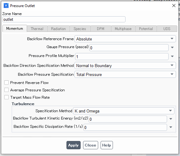 These are my reference values:n
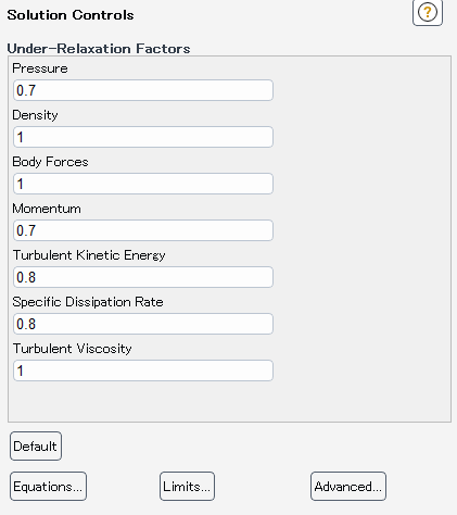
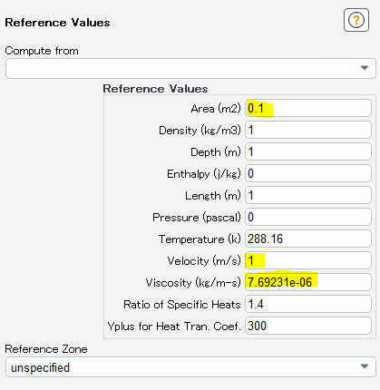 Density has not been highlighted here but it has been adjusted.nRe = 13000 = density x velocity x D / viscousity = 1 x 1 x 0.1 / ViscousitynSolution Method and Controls:n
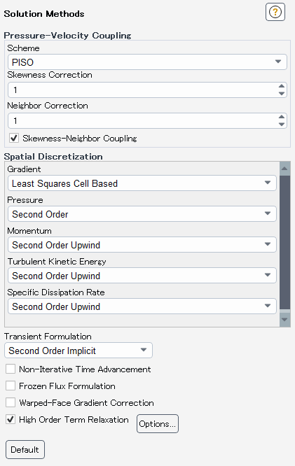
 I used Standard Initialization from Inlet:n
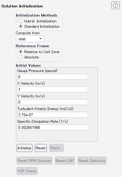 nWhat else can I do to increase my Cd value which for a Re of 13000 should be around ~2.1 but I get around ~ 1.5?.
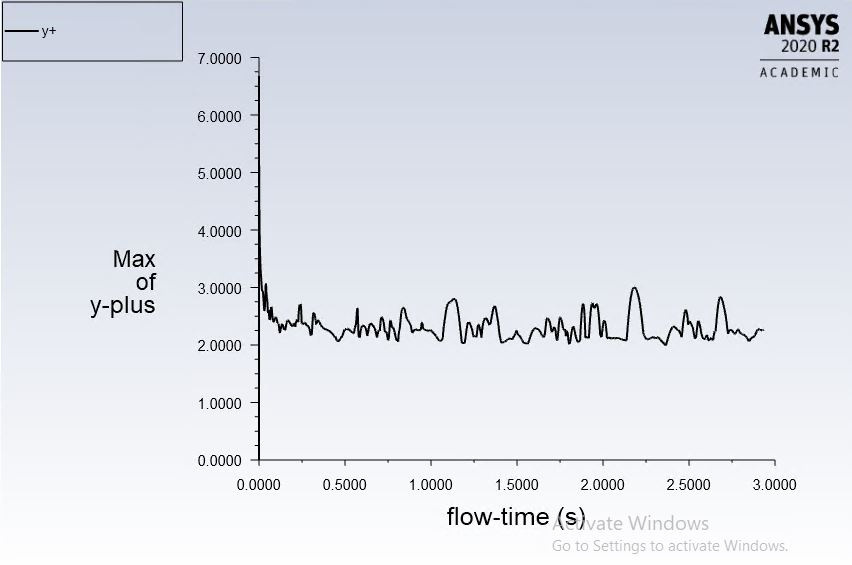
January 5, 2021 at 1:49 pmForum ModeratorIf you compare the drag with the theory how well does it compare? Looking at the results there is a transient in the solution and your y+ value may be a little high for really accurate predictions. nJanuary 5, 2021 at 2:01 pmSubscribernHi Rob,nThank you for your response.nComparing with the Literature, for Reynold's Number = 13000, with turbulence intensity of <0.06%, the Cd value for Square is close to ~2.1 . I am simulating under the same conditions and I get around ~1.7nThis mesh's first cell height is 0.01 m (D/10), I tried running with 0.005 m (D/20), a little finer mesh, but it didn't really change much.nI have run a D/1000 mesh (first cell height = 0.0001 m) but it is too computationally expensive and the results have no order (I ran for just 4 seconds though, took me 3 days). Y+ was very low for this case, close to 1. nJanuary 5, 2021 at 2:13 pm
nWhat else can I do to increase my Cd value which for a Re of 13000 should be around ~2.1 but I get around ~ 1.5?.
January 5, 2021 at 1:49 pmForum ModeratorIf you compare the drag with the theory how well does it compare? Looking at the results there is a transient in the solution and your y+ value may be a little high for really accurate predictions. nJanuary 5, 2021 at 2:01 pmSubscribernHi Rob,nThank you for your response.nComparing with the Literature, for Reynold's Number = 13000, with turbulence intensity of <0.06%, the Cd value for Square is close to ~2.1 . I am simulating under the same conditions and I get around ~1.7nThis mesh's first cell height is 0.01 m (D/10), I tried running with 0.005 m (D/20), a little finer mesh, but it didn't really change much.nI have run a D/1000 mesh (first cell height = 0.0001 m) but it is too computationally expensive and the results have no order (I ran for just 4 seconds though, took me 3 days). Y+ was very low for this case, close to 1. nJanuary 5, 2021 at 2:13 pmKarthik Remella
AdministratorHi,nFor drag estimations, as mentioned, the y+ values must be close to 1.nAnother thought that comes to mind: because you are solving a transient problem, you might want to make sure that you are converging every single time-step. Improper convergences can also lead to discrepancies.nAlso, I don't understand your comment on 'results have no order'. Can you please explain it?nKarthiknJanuary 5, 2021 at 2:26 pmSubscribernnThank you for responding.nI will try using the D/1000 mesh again then. It just takes too much time though. My colleague and I, are using the same mesh so I can't alter the mesh as much as I want to. nAs you can see in the residuals in my post, the residuals start diverging after a while, is reducing the relaxation factor all I can do to ensure that the residuals decrease or converge? I am already running second order for all discretization fields.nRegarding results having no order, the results for all Cd, Cl, and Cm are not organized in the sense they don't show a pattern, all of those plots were like the residual graph I have attached for this post. (I am home so I don't have the screenshots here, I can attach them tomorrow).nnJanuary 5, 2021 at 3:31 pmAdministratorBecause you are using PISO, you can leave your Solution Controls relatively high. nAlso, one more thing to keep in mind - your problem could be inherently transient. Have you thought about that?nKarthiknJanuary 5, 2021 at 4:48 pmSubscribernThank you for the response. So I can keep my relaxation factors relatively high, I hope is what you mean to say. nI don't exactly understand what you mean by inherently transient?nI am simulating a typical case of flow past a square cylinder, It is transient so I am not using steady but transient simulation.nnJanuary 6, 2021 at 7:31 amSubscribernThis is the simulation results with k-w SST PISO (First boundary layer = D/1000 Mesh where D = 0.1m) with a time step size of 5x10^-5. This is what I meant by disorder.n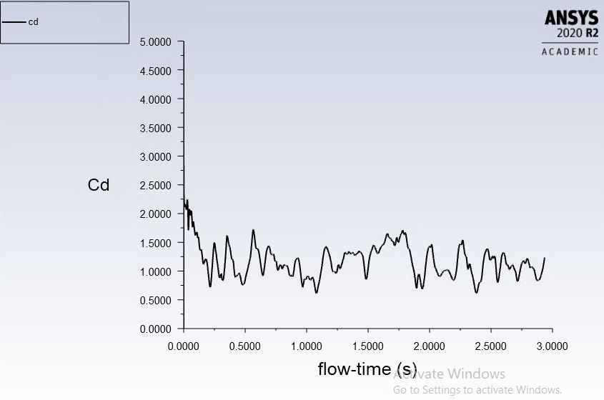


 n
January 6, 2021 at 7:43 amSubscriberIn my understanding PISO is much better than SIMPLEC but it seems PISO gives troubles for my case. I tried switching to SIMPLEC (first the residuals were increasing with every iteration right after starting simulation but then on using Higher-Order Relaxation the residuals decreased) but the residuals keep on diverging. I am trying to control it by reducing the under-relaxation factors as per Fluent Manual Recommendation (For SIMPLEC the manual recommends the Pressure need not necessarily be changed. Is there anything else I could do?nThank you.n
n
January 6, 2021 at 7:43 amSubscriberIn my understanding PISO is much better than SIMPLEC but it seems PISO gives troubles for my case. I tried switching to SIMPLEC (first the residuals were increasing with every iteration right after starting simulation but then on using Higher-Order Relaxation the residuals decreased) but the residuals keep on diverging. I am trying to control it by reducing the under-relaxation factors as per Fluent Manual Recommendation (For SIMPLEC the manual recommends the Pressure need not necessarily be changed. Is there anything else I could do?nThank you.n The results are much more ordered but then the Cd value is still low.n


 January 6, 2021 at 9:53 amForum ModeratorWhat's the mesh like in the shedding/separation region? Remember y+ is only the first cell height, the inflation layer thickness and cell density also matter. nPISO is better for transient runs, and I'd tend to favour PBCS for most applications now over SIMPLE(C). If it's transient relaxing the PBCS Courant Number or time factor can help but you then may be smearing out real transient flow features. nJanuary 6, 2021 at 10:18 amSubscribernnThank you for your response. I am attaching the general picture of the mesh and also the area of flow separation. My colleague used the same mesh for Openfoam simulation and got good results.n
 The inflation layer thickness is 0.00001 m and there are 11 layers of the same thickness. Moving away from these 11 layers, the shape isn't a perfect rectangle/square but the thickness is close to the inflation layer thickness for many more layers.n
 I tried using PISO but the solution always diverges (Either I get Floating Point Error or Convergence issues after running for a while). SIMPLEC is much better in that aspect but the Cd value is still low. I haven't tried PBCS yet so I do not have much idea about it.n
January 6, 2021 at 10:54 amForum ModeratorNow plot the velocity vectors to see what's happening. The above mesh looks OK, but I'd tend to pave the zone rather than use a block structured approach. nJanuary 6, 2021 at 11:14 amSubscriberX Velocity Vector Plotn
I tried using PISO but the solution always diverges (Either I get Floating Point Error or Convergence issues after running for a while). SIMPLEC is much better in that aspect but the Cd value is still low. I haven't tried PBCS yet so I do not have much idea about it.n
January 6, 2021 at 10:54 amForum ModeratorNow plot the velocity vectors to see what's happening. The above mesh looks OK, but I'd tend to pave the zone rather than use a block structured approach. nJanuary 6, 2021 at 11:14 amSubscriberX Velocity Vector Plotn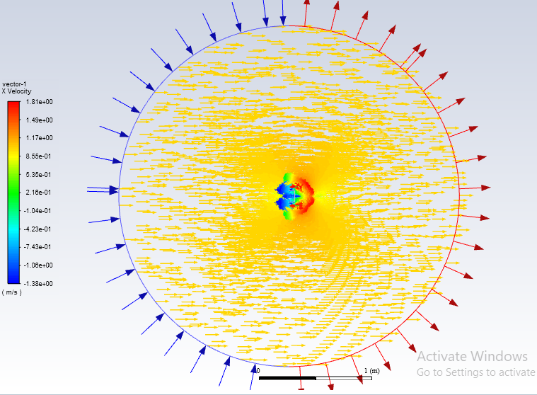 Y velocity vector Plotn
 VElocity Magnitude Vectorn
 This is a close up of the X velocity at the wall.n
 I couldn't exactly find anything odd here. The directions are as defined in the boundary condition. What else do I need to check here?n
January 6, 2021 at 11:59 amForum ModeratorThat looks fine, and shows the separation and recirculation zones nicely. Those may well be transient so as you refine the mesh it'll become less stable with the steady solver. So you may need transient (as you're using) and may need more mesh to account for the flow separation.January 6, 2021 at 2:40 pmSubscribernThank you . It's just that it takes too much time even with a mesh that's this fine. Takes me around 2 days and one night to simulate around 3 seconds worth of simulation time. Any tips on how to reduce this time?nI tried using NITA (Non-iterative Time Advancement) but with the Higher-Order Term Relaxation off I find that it is less stable. I just started with it so I think I am not very good at setting the parameters.nAnother thing is diverging residuals (as shown in the residual picture in this thread), I am not sure what I can do converge them?nI tried decreasing the Under Relaxation Factor but as I find it it just scales down the divergence of the residual but the residuals continue to diverge.nThanks for your time. nJanuary 6, 2021 at 3:00 pmForum ModeratorIf NITA is struggling and turning HOTR on helps you may need to reduce the time step. That'll also help with more general convergence: reducing UR factors is less useful in transient simulations. nRe speeding up calculations, use more computers, plan ahead and wait. CFD solutions, especially transient, aren't always done in a few days. nJanuary 6, 2021 at 3:05 pmSubscriberThank you. This forum has been of great help to students like me. The Cd hasn't still gone up but I I will update you on what happens with the solution as it continues for a longer period of time. nI did reduce the time-step. That lowered the residuals but didn't quite help with the divergence. But, thank you. I will remember regarding reducing UR factors in transient simulations. nUnderstood. Thanks.nJanuary 7, 2021 at 9:02 amSubscriberI continued the experiment and the Cd values are coming up to the expected value now, so that's good news. I will attach a snapshot.n
I couldn't exactly find anything odd here. The directions are as defined in the boundary condition. What else do I need to check here?n
January 6, 2021 at 11:59 amForum ModeratorThat looks fine, and shows the separation and recirculation zones nicely. Those may well be transient so as you refine the mesh it'll become less stable with the steady solver. So you may need transient (as you're using) and may need more mesh to account for the flow separation.January 6, 2021 at 2:40 pmSubscribernThank you . It's just that it takes too much time even with a mesh that's this fine. Takes me around 2 days and one night to simulate around 3 seconds worth of simulation time. Any tips on how to reduce this time?nI tried using NITA (Non-iterative Time Advancement) but with the Higher-Order Term Relaxation off I find that it is less stable. I just started with it so I think I am not very good at setting the parameters.nAnother thing is diverging residuals (as shown in the residual picture in this thread), I am not sure what I can do converge them?nI tried decreasing the Under Relaxation Factor but as I find it it just scales down the divergence of the residual but the residuals continue to diverge.nThanks for your time. nJanuary 6, 2021 at 3:00 pmForum ModeratorIf NITA is struggling and turning HOTR on helps you may need to reduce the time step. That'll also help with more general convergence: reducing UR factors is less useful in transient simulations. nRe speeding up calculations, use more computers, plan ahead and wait. CFD solutions, especially transient, aren't always done in a few days. nJanuary 6, 2021 at 3:05 pmSubscriberThank you. This forum has been of great help to students like me. The Cd hasn't still gone up but I I will update you on what happens with the solution as it continues for a longer period of time. nI did reduce the time-step. That lowered the residuals but didn't quite help with the divergence. But, thank you. I will remember regarding reducing UR factors in transient simulations. nUnderstood. Thanks.nJanuary 7, 2021 at 9:02 amSubscriberI continued the experiment and the Cd values are coming up to the expected value now, so that's good news. I will attach a snapshot.n I am, however, a little concerned with the trajectory of Pressure Residual and the overall residual values (k and omega seem stable but are oscillating at a value of around1e-3 and 1e-4). I am using a time step size of 5e-5 right now and I know that the residuals will decrease by decreasing the timestep size but the trajectory remains the same.nI am concerned about the trajectory and oscillation amplitude of Pressure residual.n
 What can be done to make pressure residual to converge? I am not sure if I am just lucky that the Cd values are now stabilizing, even though the pressure is diverging.n
January 7, 2021 at 11:35 amForum ModeratorThat looks OK, the continuity will drift a bit but as long as it converges every step you're fine. Note the solver only retains a certain amount of residual data so the plots can look odd outside of that range: look at the section over about 163500 iterations, it's fairly level. nViewing 22 reply threads
What can be done to make pressure residual to converge? I am not sure if I am just lucky that the Cd values are now stabilizing, even though the pressure is diverging.n
January 7, 2021 at 11:35 amForum ModeratorThat looks OK, the continuity will drift a bit but as long as it converges every step you're fine. Note the solver only retains a certain amount of residual data so the plots can look odd outside of that range: look at the section over about 163500 iterations, it's fairly level. nViewing 22 reply threads- The topic ‘Cd Value is lower than expected.’ is closed to new replies.
Innovation Space Trending discussions
 Top Contributors
-
peteroznewman
 6495
6495 -
scabo
 1906
1906 -
Dennis Chen
 1458
1458 -
javat33489
 1308
1308 -
Shyam Prasad V Atri
1022
Top Rated Tags
© 2026 Copyright ANSYS, Inc. All rights reserved.
Ansys does not support the usage of unauthorized Ansys software. Please visit www.ansys.com to obtain an official distribution.
-


The Ansys Learning Forum is a public forum. You are prohibited from providing (i) information that is confidential to You, your employer, or any third party, (ii) Personal Data or individually identifiable health information, (iii) any information that is U.S. Government Classified, Controlled Unclassified Information, International Traffic in Arms Regulators (ITAR) or Export Administration Regulators (EAR) controlled or otherwise have been determined by the United States Government or by a foreign government to require protection against unauthorized disclosure for reasons of national security, or (iv) topics or information restricted by the People's Republic of China data protection and privacy laws.
