

-
-
August 12, 2020 at 4:03 am
Hanantyodut
Subscribercan somebody tell me what's wrong with this condition? this is a rotating i've tried the interface setting, boundary condition setting, change the mesh method to polyhedra, cell zone setting.
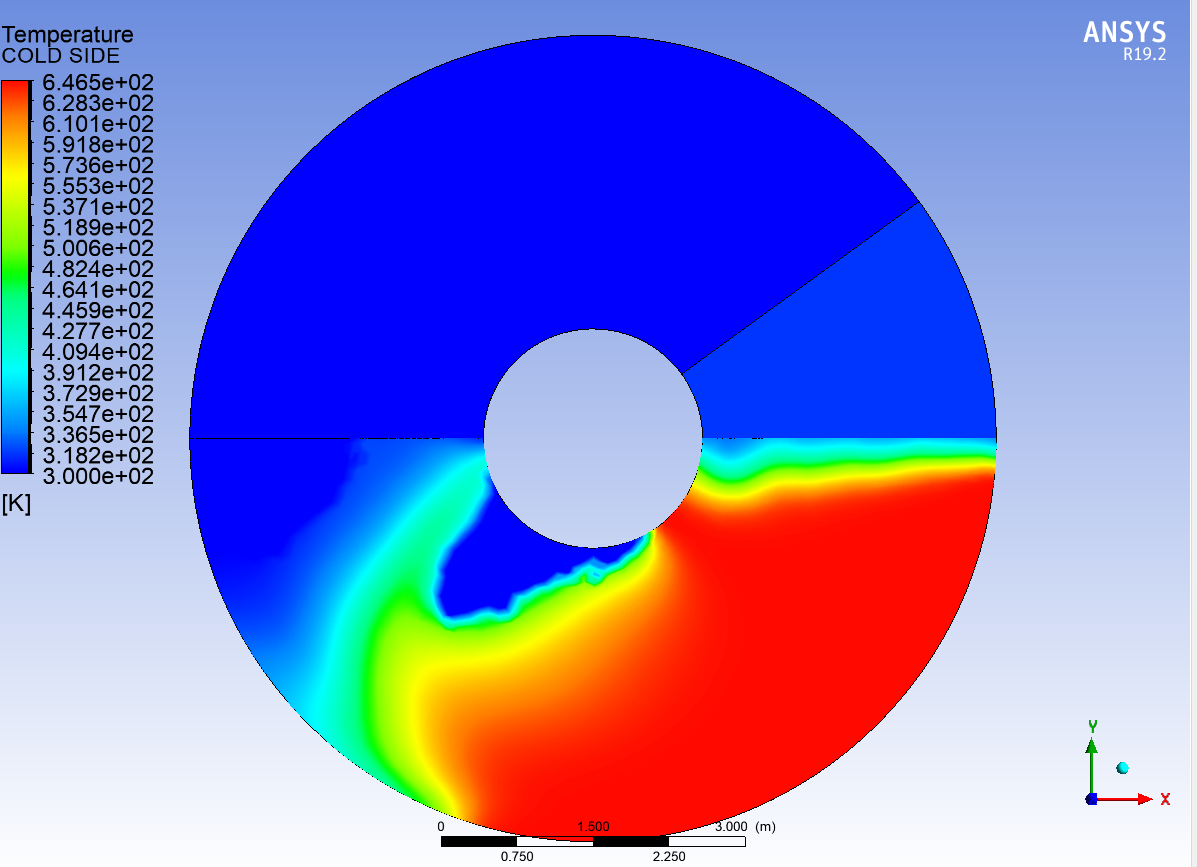
in the result, i've tried to change the scale of the temperature as user specified but still in the wrong pattern (and have a hole temperature distribution)
the 1st upper picture which is the result of my analysis...
the 2nd below picture which is the correct result. (using the same data & input)
i'll be really greatful for somebody who can give me solutions and some explanations, thanks.
August 12, 2020 at 8:36 amRob
Forum ModeratorMaybe give us some details? Perhaps starting with what it is? nAugust 12, 2020 at 9:38 amSubscriber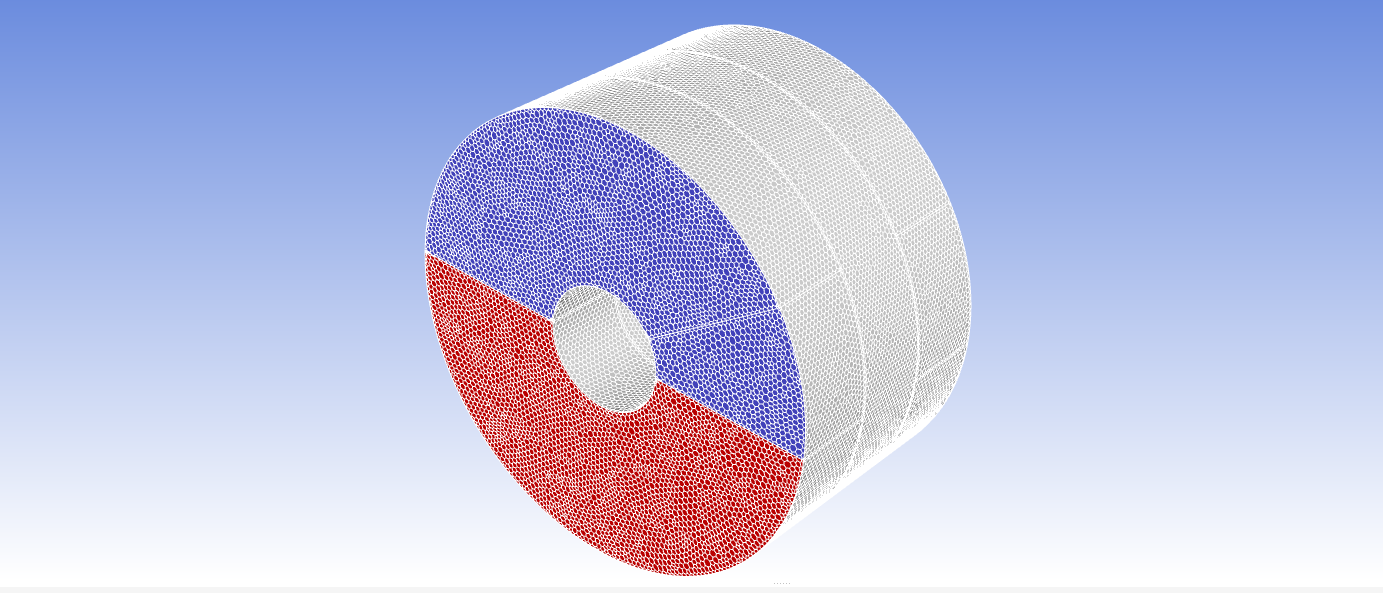 i'm sorry for the lack of information, it's a rotating heat exchanger (air preheater, tri-sector type), with 3 different condition (temp,pressure, mass flow) for the same fluid (air)n
August 12, 2020 at 11:09 amForum ModeratorWhich parts are rotating? If you review the flow field how does that compare, both to the earlier work and what you'd expect to see?nAugust 12, 2020 at 12:15 pmSubscriberFor the rotating part, which is in the middle, the other 6 part (3 part each side, primary air, secondary air, flue gas) are the fluid domain. at first i expect the flow inside the middle part (Porous fluid, solid material : steel) were to be rotating....n
i'm sorry for the lack of information, it's a rotating heat exchanger (air preheater, tri-sector type), with 3 different condition (temp,pressure, mass flow) for the same fluid (air)n
August 12, 2020 at 11:09 amForum ModeratorWhich parts are rotating? If you review the flow field how does that compare, both to the earlier work and what you'd expect to see?nAugust 12, 2020 at 12:15 pmSubscriberFor the rotating part, which is in the middle, the other 6 part (3 part each side, primary air, secondary air, flue gas) are the fluid domain. at first i expect the flow inside the middle part (Porous fluid, solid material : steel) were to be rotating....n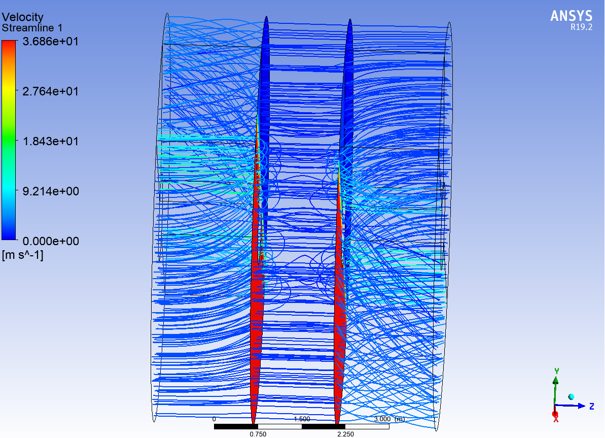 and when i saw the result domain (the end of each fluid side) i saw some clear area that have no streamline flow through them, here is the example of the view at lower RPM : n
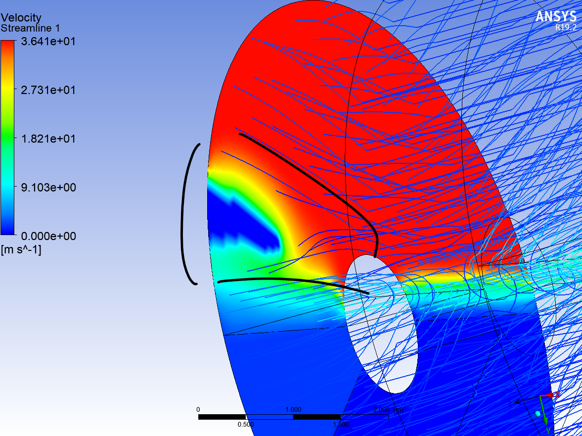 nthank you so much for your attention, i'm really thankful and hope to get the solutions for this problem.n
August 12, 2020 at 12:26 pmForum ModeratorCheck the interface conditions, and make sure you've labelled all of the surfaces correctly. I'd plot each set separately to see if one's missing. nAugust 12, 2020 at 12:49 pmSubscriberthank you for your response, i've already labelled all the interface between rotor middle part dan the fluid domain at each inlet/outlet sides. and all the wall which act as the separator i've set them as coupled wall between 3 fluids. And for the interfaces i've set them as periodic boundary conditionn
nthank you so much for your attention, i'm really thankful and hope to get the solutions for this problem.n
August 12, 2020 at 12:26 pmForum ModeratorCheck the interface conditions, and make sure you've labelled all of the surfaces correctly. I'd plot each set separately to see if one's missing. nAugust 12, 2020 at 12:49 pmSubscriberthank you for your response, i've already labelled all the interface between rotor middle part dan the fluid domain at each inlet/outlet sides. and all the wall which act as the separator i've set them as coupled wall between 3 fluids. And for the interfaces i've set them as periodic boundary conditionn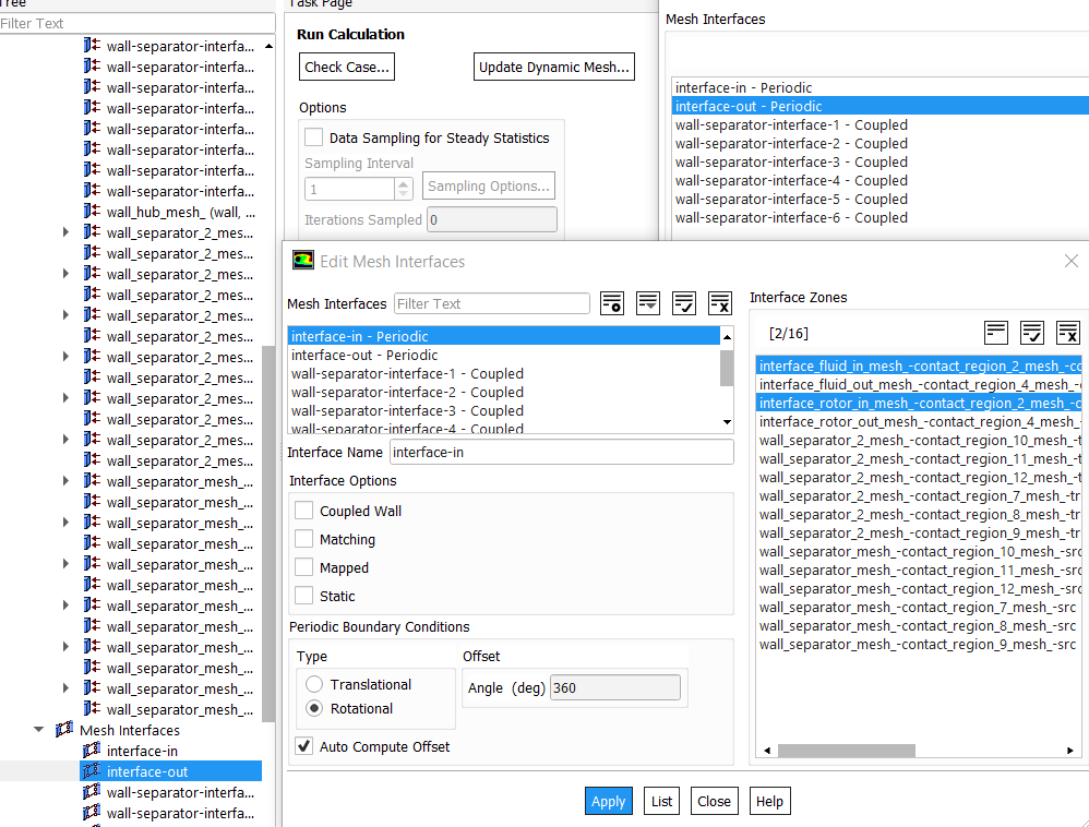 n
August 12, 2020 at 3:09 pmForum ModeratorWhy periodic, doesn't flow pass through the system once? Very carefully look at what is wall and what isn't, looking at the shear number of bc's I think there's ample scope for errors to creep in to the set-up. nAugust 12, 2020 at 3:29 pmSubscriberthank you, may i ask at what setting/setup option to cause the interface become a frozen rotor?because yes it's rotating continuosly that means the setting of my interface is wrong and actually not periodic ones....nfor the wall, i'm already check all of it and from my assumption it's correct? i'm sorry , suggestions are welcome...nthis is the wall that separate the 3 fluids, the hub in the center of the APH, and the outer wall of the fluid and the rotor.n
n
August 12, 2020 at 3:09 pmForum ModeratorWhy periodic, doesn't flow pass through the system once? Very carefully look at what is wall and what isn't, looking at the shear number of bc's I think there's ample scope for errors to creep in to the set-up. nAugust 12, 2020 at 3:29 pmSubscriberthank you, may i ask at what setting/setup option to cause the interface become a frozen rotor?because yes it's rotating continuosly that means the setting of my interface is wrong and actually not periodic ones....nfor the wall, i'm already check all of it and from my assumption it's correct? i'm sorry , suggestions are welcome...nthis is the wall that separate the 3 fluids, the hub in the center of the APH, and the outer wall of the fluid and the rotor.n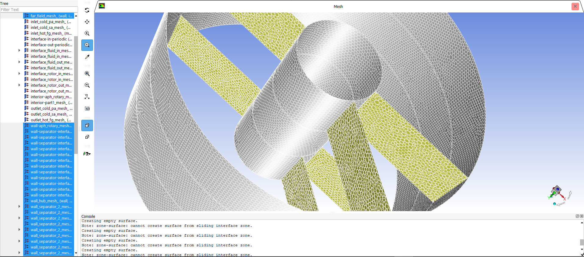 thank you so much.n
August 14, 2020 at 12:28 pmSubscriberthe wall inside the fluid domain (yellow) i set them coupled in the setting. nfor the wrong temperature distribution do you have any advice or explanation? i would be really thankful and grateful to anybody for some suggestion and solution for this problem..nAugust 14, 2020 at 1:55 pmForum ModeratorIf it's a wall try and model it as such, for the sliding zones use the non-conformal interface(s). There's a tutorial in the Fluent help that's very good: it's a mixing tank but the basic physics & set-up will help. nAugust 14, 2020 at 3:23 pmSubscriberthank you, that means that my simulation time model in transient? do the middle part should have mesh motion? or frame motion for it's rotational movement enough?nand for the non-conformal mesh means the geometry of the middle rotor must partially overlap the both fluid domains (inlet&outlet)?n nAugust 14, 2020 at 3:52 pmForum ModeratorI assumed it was rotating about the axis, with inlet(s) at one end and outlet(s) at the other. Interface zones touch on the surface, so overlap in that respect, the volumes do NOT overlap. nAugust 14, 2020 at 4:26 pmSubscriberthank you for your response, i'm sorry for the inconvenience...nmy interfaces already touch on the surface, does that means the mesh type is sliding meshes? and for the simulation time method should use the transient type?nthank you so much..nAugust 17, 2020 at 10:43 amForum ModeratorIt means you have the option to use sliding mesh, and if sections are rotating at different rates it'll be transient. nViewing 14 reply threads
thank you so much.n
August 14, 2020 at 12:28 pmSubscriberthe wall inside the fluid domain (yellow) i set them coupled in the setting. nfor the wrong temperature distribution do you have any advice or explanation? i would be really thankful and grateful to anybody for some suggestion and solution for this problem..nAugust 14, 2020 at 1:55 pmForum ModeratorIf it's a wall try and model it as such, for the sliding zones use the non-conformal interface(s). There's a tutorial in the Fluent help that's very good: it's a mixing tank but the basic physics & set-up will help. nAugust 14, 2020 at 3:23 pmSubscriberthank you, that means that my simulation time model in transient? do the middle part should have mesh motion? or frame motion for it's rotational movement enough?nand for the non-conformal mesh means the geometry of the middle rotor must partially overlap the both fluid domains (inlet&outlet)?n nAugust 14, 2020 at 3:52 pmForum ModeratorI assumed it was rotating about the axis, with inlet(s) at one end and outlet(s) at the other. Interface zones touch on the surface, so overlap in that respect, the volumes do NOT overlap. nAugust 14, 2020 at 4:26 pmSubscriberthank you for your response, i'm sorry for the inconvenience...nmy interfaces already touch on the surface, does that means the mesh type is sliding meshes? and for the simulation time method should use the transient type?nthank you so much..nAugust 17, 2020 at 10:43 amForum ModeratorIt means you have the option to use sliding mesh, and if sections are rotating at different rates it'll be transient. nViewing 14 reply threads- The topic ‘wrong temperature distribution in the result, solutions & advice?’ is closed to new replies.
Innovation Space Trending discussions
- air flow in and out of computer case
- Varying Bond model parameters to mimic soil particle cohesion/stiction
- Eroded Mass due to Erosion of Soil Particles by Fluids
- I am doing a corona simulation. But particles are not spreading.
- Centrifugal Fan Analysis for Determination of Characteristic Curve
- Issue to compile a UDF in ANSYS Fluent
- Guidance needed for Conjugate Heat Transfer Analysis for a 3s3p Li-ion Battery
- JACOBI Convergence Issue in ANSYS AQWA
- affinity not set
- Resuming SAG Mill Simulation with New Particle Batch in Rocky
Top Contributors
-
peteroznewman
 4177
4177 -
scabo
 1493
1493 -
Dennis Chen
 1363
1363 -
javat33489
 1196
1196 -
Shyam Prasad V Atri
1021
Top Rated Tags
© 2025 Copyright ANSYS, Inc. All rights reserved.
Ansys does not support the usage of unauthorized Ansys software. Please visit www.ansys.com to obtain an official distribution.
-


The Ansys Learning Forum is a public forum. You are prohibited from providing (i) information that is confidential to You, your employer, or any third party, (ii) Personal Data or individually identifiable health information, (iii) any information that is U.S. Government Classified, Controlled Unclassified Information, International Traffic in Arms Regulators (ITAR) or Export Administration Regulators (EAR) controlled or otherwise have been determined by the United States Government or by a foreign government to require protection against unauthorized disclosure for reasons of national security, or (iv) topics or information restricted by the People's Republic of China data protection and privacy laws.


