Ansys Assistant will be unavailable on the Learning Forum starting January 30. An upgraded version is coming soon. We apologize for any inconvenience and appreciate your patience. Stay tuned for updates.
Photonics

Photonics

Topics related to Lumerical and more.

How to determine the correct T as the xy span region changes?

TAGGED: 

    • 10172100207
      Subscriber

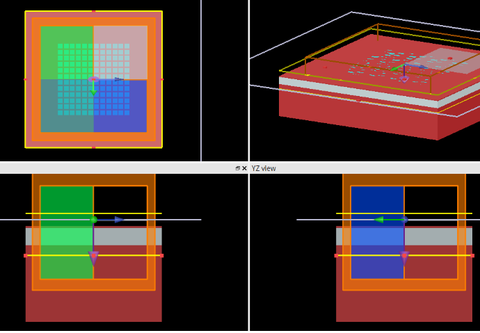
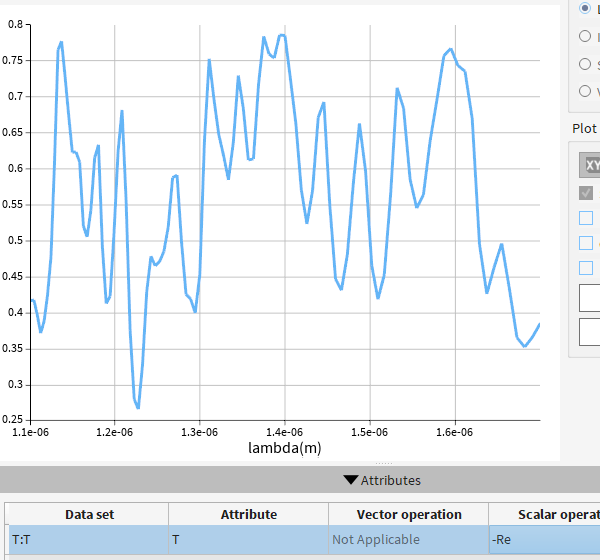
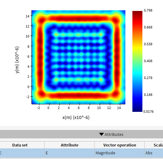
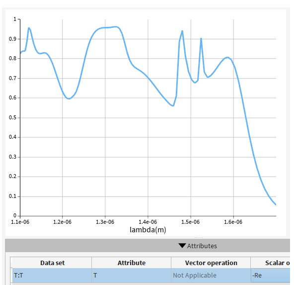
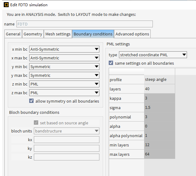
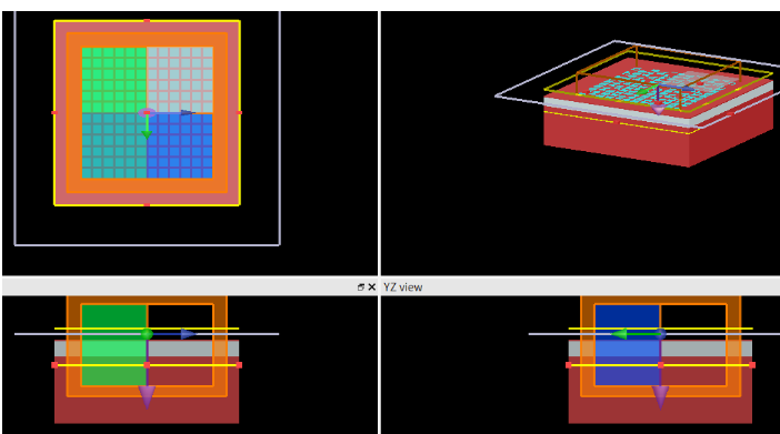
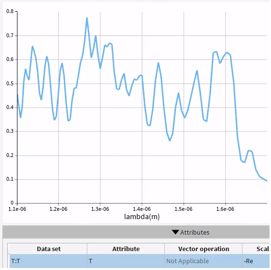
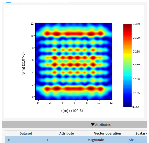
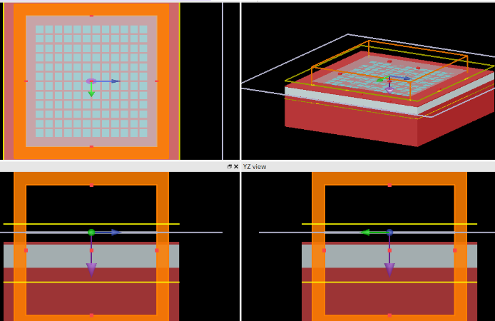
      "I want to simulate the transmission spectrum of a finite periodic structure. How should I set the FDTD boundary conditions correctly? I have simulated several scenarios, but I don't know which one is correct. The first scenario is my reference simulation, where I assume the period is infinite. In this case, all FDTD boundary conditions are set to periodic. Specifically, I chose anti-symmetric boundary conditions for x min and x max, symmetric boundary conditions for y min and y max, and PML for z. The simulation region is one unit cell. The FDTD xy region size is the period of the unit cell. The boundary settings, structure, transmission monitor's T, and electric field are as follows:

      However, I want to simulate a finite periodic array.

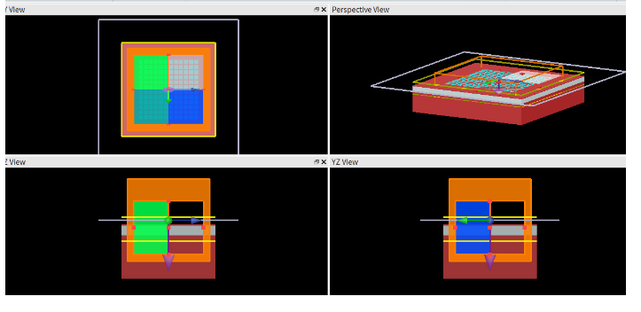
      I set up simulations with three different FDTD regions, all with the same FDTD settings, as follows:

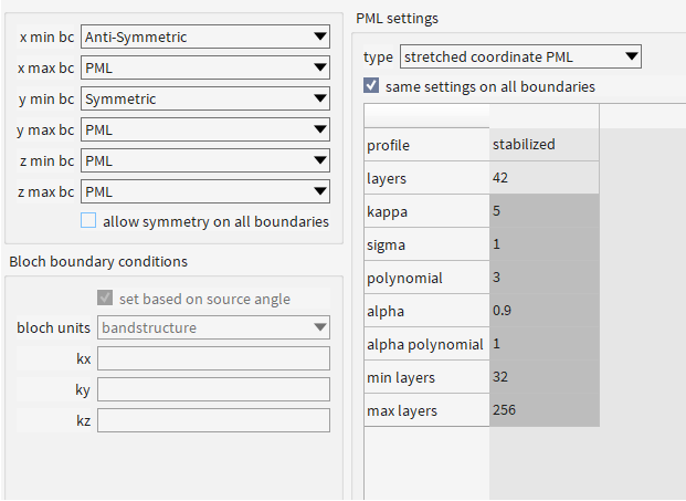
      The first simulation has an FDTD x span and y span = 12.6um:

      The second simulation has an FDTD x span and y span = 14.6um:

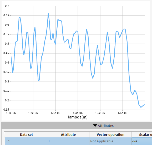
      The third simulation has an FDTD x span and y span = 18.6um:

    • Kirill
      Forum Moderator

      Dear Subscriber,

      If you want to simulate periodic boundary conditions, you should ensure that the simulation period matches the period of your structure.

      Best regards,
      Kirill

      • 10172100207
        Subscriber

        When I use periodic boundary conditions in FDTD, it assumes an infinitely periodic structure, and I ensure that the simulation period matches the period of your structure. However, now I want to simulate a finite periodic structure, so my boundary conditions should be set to PML. What I need to determine is, for a finite periodic structure, the influence of the FDTD simulation cross-sectional dimensions in the xy directions on the transmittance results - how to set the xy span size to obtain correct transmittance results. Thanks!

    • 10172100207
      Subscriber

      Hi, when I use periodic boundary conditions in FDTD, it assumes an infinitely periodic structure, and I ensure that the simulation period matches the period of your structure. However, now I want to simulate a finite periodic structure, so my boundary conditions should be set to PML. What I need to determine is, for a finite periodic structure, the influence of the FDTD simulation cross-sectional dimensions in the xy directions on the transmittance results - how to set the xy span size to obtain correct transmittance results. Thanks!

    • Kirill
      Forum Moderator

      Dear Subscriber,

      A periodic structure is infinite by definition, whereas a finite structure is non-periodic. When using PML boundary conditions, you're simulating a finite, non-periodic structure, including the effects of both the structure and the source.
      Changing the x and y span effectively changes both the physical size of the structure being simulated and the side area along its perimeter. As a result, it's expected that the transmittance results will also change. This is not an error, it simply reflects the behavior of different structures.
      Additionally, since the source is no longer perfectly matched to an infinite periodic structure, you observe edge diffraction effects from the source and the finite boundaries.

      Best regards,
      Kirill

      • 10172100207
        Subscriber

        How can the effects of diffraction be eliminated? Thank you.

    • Kirill
      Forum Moderator

      Dear Subscriber,

      I guess there is no simple way around this; it's the nature of wave propagation. Without edges, there will be no edge diffraction. So, using only periodic BCs, I suppose.

      Best regards,
      Kirill


      • 10172100207
        Subscriber

        Can I use TFSF to calculate the transmittance? As far as I know, TFSF is generally used to calculate scattering and absorption. If I use a Gaussian source, according to the formula for calculating transmittance, the integral area of the monitor and the area of the Gaussian source are different, which could lead to incorrect transmittance calculations. So, can I only use a plane wave to obtain a roughly accurate transmittance.

    • Kirill
      Forum Moderator

      Dear Subscriber, 

      In order to assist you further, could you please provide the following:

      Which operating system and version of Lumerical are you using? Please send a screenshot of the Lumerical CAD > Help > About... page, which provides this information (like this image). 

      Thank you! 

      • 10172100207
        Subscriber

        [ The image has been deleted. ] 

         Hi, the information is : 


    • Kirill
      Forum Moderator

      Sorry, but we were unable to verify the account in our system. Please provide us with the name of the channel partner or Ansys account manager from whom you purchased the licenses in order to proceed with support. Thank you! 

Viewing 6 reply threads
  • You must be logged in to reply to this topic.
[bingo_chatbox]