-
-
April 2, 2020 at 7:25 pm
j.drozdowski
SubscriberHello. I've got a question regarding load applying in workbench. Below you can find some picture showing my test model. It is simple deck stiffened with flat bars.There is a stiff crate laying on it. The only load is a dead load.
In this test model i made a contact between box and deck to clearly show what I'm looking for. It is often that the object which is loading the construction is much stiffer than the construction itself ( some cargo laying on deck or some very heavy maschine ). So after deflection the load is not "following" the deformation.
It is easy to use contact in this test model but if it would be real design with lot of different construction members it is impossible to analyze contact every time.

I'm wondering is it possible to delete crate from this model and replace it with distributet load which won't follow the deformation - to properly simulate what is really happening.
I assume that using force or pressure component is not an answer in this case. Please correct me if I'm wrong.
-
April 2, 2020 at 7:31 pm
Wenlong
Ansys EmployeeHi,
You can check remote force, with the behavior set to rigid. Please check out this relevant post: /forum/forums/topic/adding-load-to-2d-rigid-surface/?order=all#comment-cf24a20e-abe7-4c3d-a7c9-ab8e01488b00
Regards,
Wenlong
Useful Links
- How to access Ansys Online Help Document
- How to show full resolution image
- How to use Google to search within Ansys Student Community
-
April 2, 2020 at 11:37 pm
peteroznewman
SubscriberIf you use just two lines of force, one for each edge of the box, those forces don't change direction or add any false bending moment to the deck as the deformation occurs.
-
April 3, 2020 at 1:40 pm
j.drozdowski
SubscriberThank you Sirs very much for you responses.
@Wenlong
I'm afraid that effect will be different. Using remote force component
it will connect point load with the surface through the RBE (rigid or deformable). But It will still follow the deformation. And what worse it will add extra stiffness to the surface which it is applied.
@Peter
I know wat you mean. In this particular case it is quite easy to anticipate how the structure will deflect and where the load will be applied. But in some more complicated case with different loads and more complicated structure it won't be so easy.
My question is:
Is there any component or procedure in Ansys to apply equivalent load of the box weight targeting it to surface but taking into account the effect I described earlier. So this component should apply more load to more rigid region and less load to more flexible region. But maybe there is no such a thing and the proper distribution should be made by hand.
Regards. -
April 3, 2020 at 2:12 pm
peteroznewman
SubscriberTo get an accurate load distribution, use frictional contact between the bottom of the box and the deck, but that results in high computational effort, even when the box is a rigid body as there are many nodes on the deck that need to be checked.
To get low computational effort, with some loss of accuracy, apply four nodal forces equal to 1/4 of the weight of the box to nodes on the deck where the four corners of the box are located and don't have a box.
An intermediate position is to use frictional contact between just four deck nodes, one near each of the four corners, to the rigid box. That will be much less computational effort than the first case but more accurate than just using four forces.
-
April 3, 2020 at 6:21 pm
Wenlong
Ansys EmployeeHi,
Sorry I didn't read your post carefully and provided an unrelated response. I have a question about the crate shape, you mentioned in reality the crate shape can be complex, in that case, you will have to model the exact shape and define contact, right?
Regards,
Wenlong
-
April 5, 2020 at 5:16 pm
j.drozdowski
SubscriberHi.
I would rather assume that the supporting construction can be more complex than in my test model so the deflection won't be so straightforward and area of contact is hard to predict. But you are absolutely right the crate also can be more complex or it can be also some complex-shape maschine loading a construction.
I just thought that maybe there is an easy tool to avoid contact in such a cases. But it seems that sometimes contact is a must.
Thank you Sirs for your suggestions. -
May 8, 2023 at 9:32 am
Abhijeet Chilwirwar
SubscriberI am unable to make a new discussion therefore writting here my doubts.
I have been trying to simulate a hip implant in Ansys WB but I am constantly getting same errors. I have many similar discussions on this portal, some were relevant I tried them but nothing worked. I am applying compressive load of 2.3 kN on a hip implant placed inside an acrylic cement everything supported by a SS holder. No meshing error is been shown but solution is the same "An Internal solution magnitude limit wasexceeded. Please check your environment for inapppropriate load values or insufficient supports." And point to note is that when I am applying load using global co-ordinate axis then position of force arrow is corrrect but when I am using a different co-ordinate system (which is required) then the location of force arrow gets changed(since I am using the same face to define the remote force in both the co-ordinate axis the point of location of arrow should be same). Because of this reason I had to use pressure as a load.
-
May 8, 2023 at 9:34 am
Abhijeet Chilwirwar
SubscriberI am unable to make a new discussion therefore writting here my doubts.
I have been trying to simulate a hip implant in Ansys WB but I am constantly getting same errors. I have many similar discussions on this portal, some were relevant I tried them but nothing worked. I am applying compressive load of 2.3 kN on a hip implant placed inside an acrylic cement everything supported by a SS holder. No meshing error is been shown but solution is the same "An Internal solution magnitude limit wasexceeded. Please check your environment for inapppropriate load values or insufficient supports." And point to note is that when I am applying load using global co-ordinate axis then position of force arrow is corrrect but when I am using a different co-ordinate system (which is required) then the location of force arrow gets changed(since I am using the same face to define the remote force in both the co-ordinate axis the point of location of arrow should be same). Because of this reason I had to use pressure as a load.
Help me with this. Attaching some relevant photos. Thanking you.


-
- The topic ‘
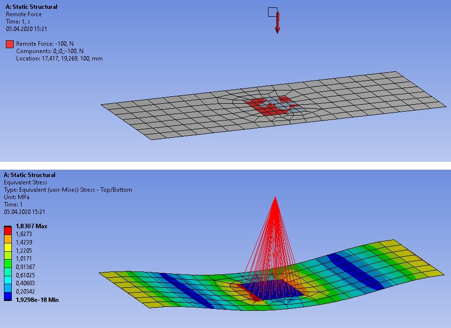
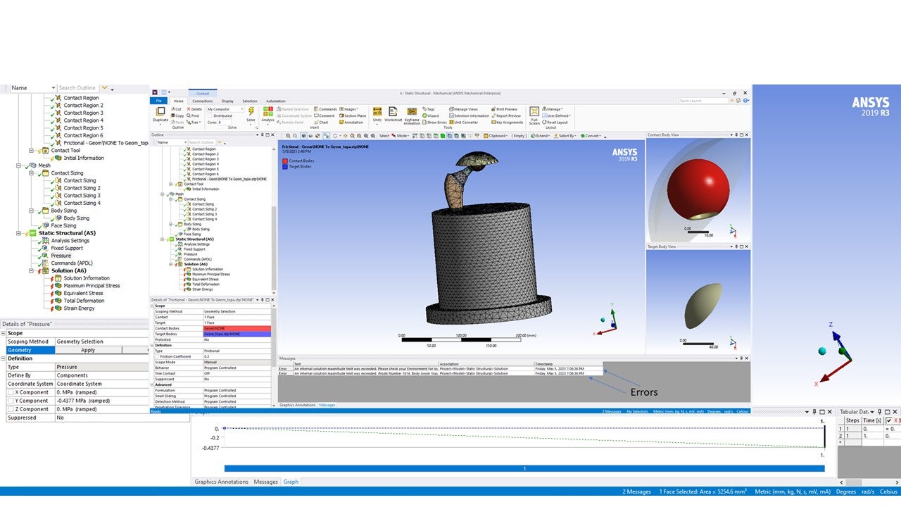
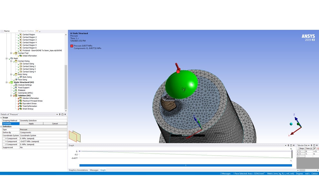
Applying “rigid” load – not following the deformation’ is closed to new replies.
-
6495
-
1906
-
1458
-
1308
-
1022
© 2026 Copyright ANSYS, Inc. All rights reserved.

