-
-
March 6, 2023 at 10:01 am
-
March 6, 2023 at 11:02 am
SRP
Ansys EmployeeHi,
I suggested to try remeshing the geometry with finer mesh along with it try to capture the curvature.
Have a look at the video provided here:
Thank you.
-
March 6, 2023 at 2:29 pm
peteroznewman
SubscriberYou could change the colors on the Legend to match the colors used in the second image and also make the values for each color bar match the values used in the second image.
Then you should turn off the Mesh in the image so all you see are the contours. Hard to see the color under all those black lines.
-
March 7, 2023 at 9:22 am
Mo
SubscriberHi there,
Â
 I have applied finer meshing across the hole as this is where the results are being taken from and reduced meshing elsewhere to save on computational time, do you think my boundary condtions have been loaded incorrecetly. Below I have an image of the component within the machine, and the boundary condtions I have given to my component and the load is indicated as 50 kN:
Â
And regarding the colur change for the legend, how would I manage that alongisde turning off the Mesh?
Â
Thank youÂ
-
March 7, 2023 at 11:28 am
-
March 7, 2023 at 12:06 pm
Mo
SubscriberThat is what I would have done but the descrioption of the component is below:
A clevis, whose geometry is shown in Figure 1, has been tested under tensile loading to assess the level of stress concentration around the largest hole under an applied load of 50 kN. A tensile load is applied by moving the bottom crosshead of the universal testing machine (UTM) with a displacement rate of 1 mm/min, while the top crosshead is fixed. The load is applied until a value of 50 kN is measured by the load cell on the UTM.  Due to a very tight fit between the pin and the clevis and between the pin and the upper attachment after manufacturing, you may assume perfect bonding between these parts with no slippage occurring during the test.
So based on this I applied bonded contact to all the parts. What other simplifcations do you think I could do?
Â
Thank you
-
March 7, 2023 at 4:01 pm
peteroznewman
SubscriberOkay, like many exercises in school, ignore what might matter and focus on a simpler problem.
To turn off the display of the mesh, on the Results tab, pull down on the Edges button and select No Wireframe.
You can change the values on the scale by clicking on the number and typing in a new number. Sometimes you have to click on the adjacent number.
You can right click on a color and the color picker dialog opens.
-
March 7, 2023 at 4:43 pm
-
March 7, 2023 at 4:50 pm
peteroznewman
SubscriberClick on any color, notice that a box with two buttons with a + and – sign in them appear. Click on the + until the number of colors in your legend matches the number in the other legend.
Right click on the legend, one of the check marks is Min, Max appear on Color Bar. Uncheck that.
If you click on a number, doesn’t it turn into a text box that you can type into?
-
March 14, 2023 at 12:19 pm
-
March 14, 2023 at 3:17 pm
peteroznewman
SubscriberThat looks fine given that you were told to use bonded contact of the pin to the hole.
-
- The topic ‘
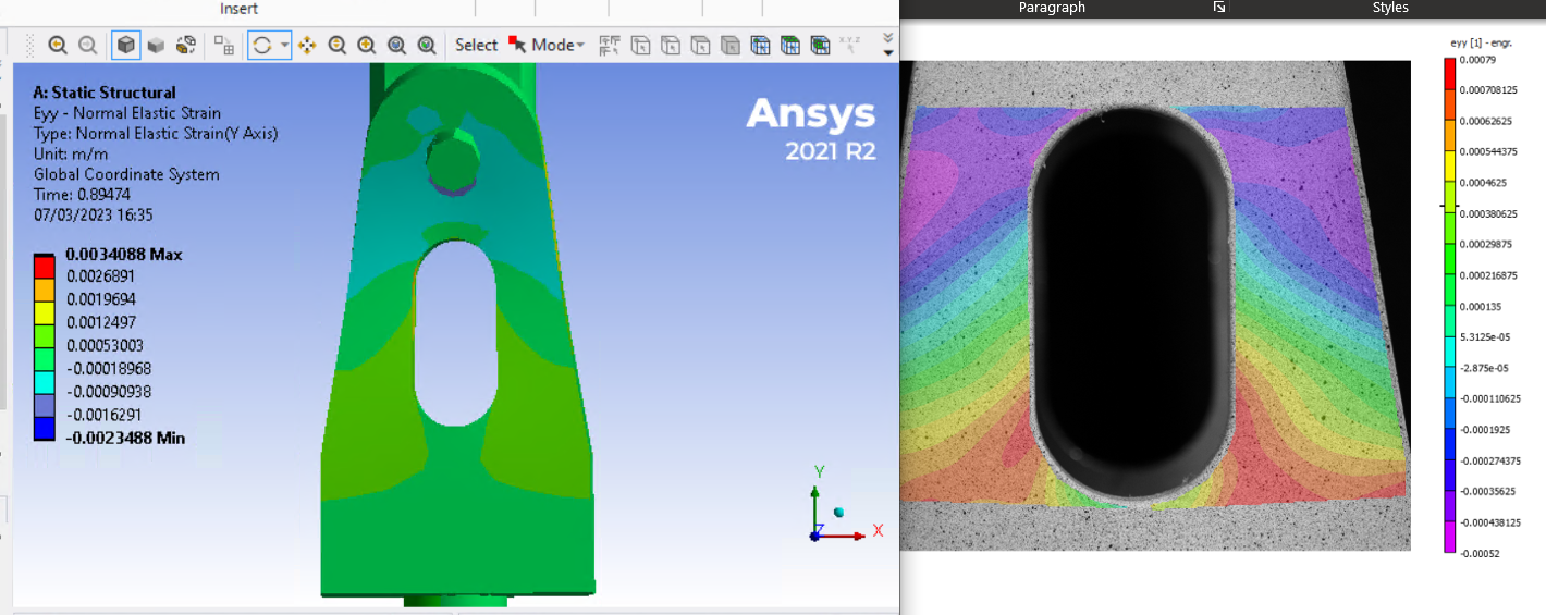
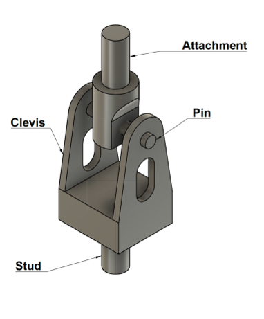
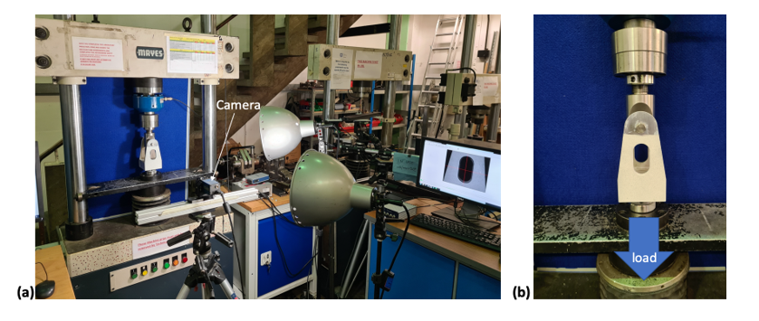
Trying to Validate Results compared to my model’ is closed to new replies.
-
6495
-
1906
-
1458
-
1308
-
1022
© 2026 Copyright ANSYS, Inc. All rights reserved.


