TAGGED: tensile
-
-
February 22, 2023 at 2:58 am
Hyeongjin Kim
SubscriberThx for your comment
-
February 22, 2023 at 7:19 am
Claudio Pedrazzi
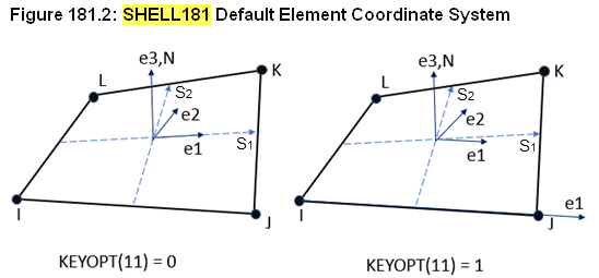
SubscriberI will answer only to a part of your question. Be careful with the element axis 11, 22, 33. Look at the element help to see how they are oriented.
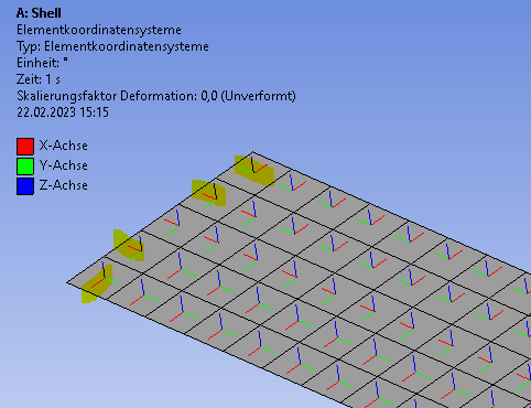
Also, you can let Workbench show you the element orientations, you have under the “results” also the possibility to create a plot with the nodal or the element coordinate systems. It is a tricky thing using those (11,22…) because it all depends on their orientation. Even for simple geometries, they are not necessarily well aligned “consistently” in one logical direction.
I advise defining your own coordinate systems, for example in your geometry possibly a cylindrical coordinate system will certainly help for some regions.
-
- The topic ‘Tensile or compression stress and bending stress each face. local element direct’ is closed to new replies.


- LPBF Simulation of dissimilar materials in ANSYS mechanical (Thermal Transient)
- Convergence error in modal analysis
- APDL, memory, solid
- Meaning of the error
- How to model a bimodular material in Mechanical
- Simulate a fan on the end of shaft
- Nonlinear load cases combinations
- Real Life Example of a non-symmetric eigenvalue problem
- How can the results of Pressures and Motions for all elements be obtained?
- Contact stiffness too big

-
4167
-
1487
-
1363
-
1194
-
1021

© 2025 Copyright ANSYS, Inc. All rights reserved.


