-
-
October 5, 2022 at 8:51 am
garazilizaso
SubscriberHi,
I am trying to simulate an indentation. I know I want to apply a 2N force in a specific axis (z), in order to provoke the simulation. The issue I'm having is that I don't want to define the displacement because I want the force to be the one that moves the indenter into the piece of substrate. The substrate is fixed in two of its sides. If I define a displacement as z being free, y = 0mm and x = 0mm, it says that the boundary conditions are invalid.
My aim is to define a for of 2N in order to create a creep (keeping the force constant during a period in order to have a constant indentation during that time) in the indentation. Can somebody help?
-
October 5, 2022 at 3:15 pm
peteroznewman
SubscriberPlease reply with a sketch of the parts and the boundary conditions.
If the substrate is a cube where the +Z face is going to be indented, then you can use a Fixed Support on the two XZ sides of the cube.
On the flat back end of the indenter, insert a Translational Joint. Apply a Joint Load of 2N. The tip of the indenter should have a small radius at the tip, not a perfectly sharp tip. That tip should be exactly tangent to the cube so that the frictional contact between the indenter and cube is initally closed. Insert a Contact Tool to verify the Initial Contact Status.
-
October 5, 2022 at 3:47 pm
garazilizaso
SubscriberThe substrate is a rectangular prism, with a non-homogeneous surface, but the tip is exactly tangent for sure. The indenter already has a small radius at the tip. The Fixed Support is defined by experimental data, so that cannot be varied. I have created a Translational Joint, but still the message of invalid boundary conditions appears. In the next picture you can see the boundary conditions, being the force application in the z axis.
-
October 5, 2022 at 8:25 pm
peteroznewman
SubscriberFor load step 1, the force starts at 0 N at t=0, and the force ramps up to 2 N at t=1 s.
For load step 2, the force can stay constant at 2 N while the creep occurs until t=2 s .
For load step 3, the force can ramp down to 0 N until t=3 s.
Reply with an image of the Coordinate System under the Translational Joint and make sure the Joint X axis is pointing along the global Z axis.
-
October 6, 2022 at 8:15 am
-
October 6, 2022 at 10:10 am
-
October 6, 2022 at 11:22 am
-
October 6, 2022 at 11:57 am
peteroznewman
SubscriberThe Translational Joint shown is a Body-Body joint. That is wrong. Delete that Joint.
Create a new Translational joint, but select Body-Ground in the Details window. Then make sure the Reference Coordinate System has the X axis pointing down.
Once that joint is created, add the Joint Load.
Under Analysis Settings, turn on Auto TIme Stepping.
Set the Initial and Minimum Substeps to 100 and the Maximum Substeps to 10000.
Turn on Large Deflection.
Under the Connections folder add a Contact Tool and Generate Initial Contact Status and check the result to make sure the contact is closed.
What kind of material model do you have for the bone?
-
October 6, 2022 at 12:09 pm
-
October 6, 2022 at 8:30 pm
peteroznewman
SubscriberWhy is the Translational Joint showing Multiple entities? There should be just one flat circular face at the top of the indenter.
You don't show what the Fixed Supports are Scoped to.
-
October 7, 2022 at 10:07 am
-
October 7, 2022 at 2:32 pm
garazilizaso
SubscriberOne of the problems is that I cannot suprress the displacement, but that is exactly what I want to do. I want to control de movement with the force. How shall I do it?
-
October 7, 2022 at 6:06 pm
peteroznewman
SubscriberYou have a Force Reaction output request in your Solution branch with a ? on it. Delete that.
Delete the Fixed Supports and create fresh copies of them. Do you still have Invalid BC error?
-
October 9, 2022 at 3:48 pm
garazilizaso
SubscriberOkay! No BC error! But now, how will I be able to analyse the force reaction output? I am interested on seeing how the force varies through out the indentation
-
October 9, 2022 at 4:10 pm
peteroznewman
SubscriberYou specified the force in the Joint Load as a function of time: [(0,0),(1,2),(2,2),(3,0)]. You can add a Probe of the Reaction Force of the Fixed Support and have Ansys plot it.
You could plot the Displacement of the Indenter as a function of time and see how the displacement changes in the 1 second while the Force is a constant value of 2 N to see how much the material creeps.
-
October 9, 2022 at 5:38 pm
garazilizaso
SubscriberNow the problem is that it doesn't converge... Even if I change the substeps and the 0N force to a really small one.
-
October 10, 2022 at 11:04 am
peteroznewman
SubscriberYou need to provide a lot more detail to make some progress on a convergence issue. What is the exact error message? Look in the Solution Output and search for the error and show some of the lines of text above that.
If you can share your model, I can take a look at it. First delete the mesh in Mechanical, then save the Project, then use File Archive in Workbench to create a .wbpz file. Put that file on a sharing site such as Google Drive, OneDrive or Jumpshare.com so anyone can download it. Reply with the link to that file.
-
October 10, 2022 at 11:34 am
garazilizaso
SubscriberYou can access to it now. Feel free to change whatever you feel like and send back any improvement you are able to make. Thank you so much
-
October 10, 2022 at 1:04 pm
peteroznewman
Subscriber
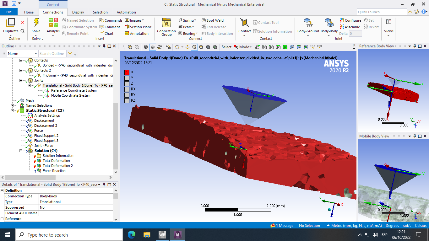
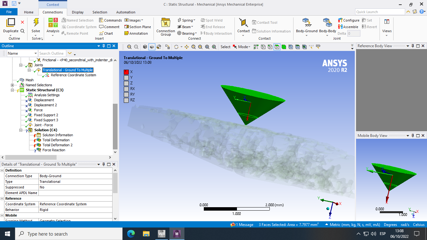
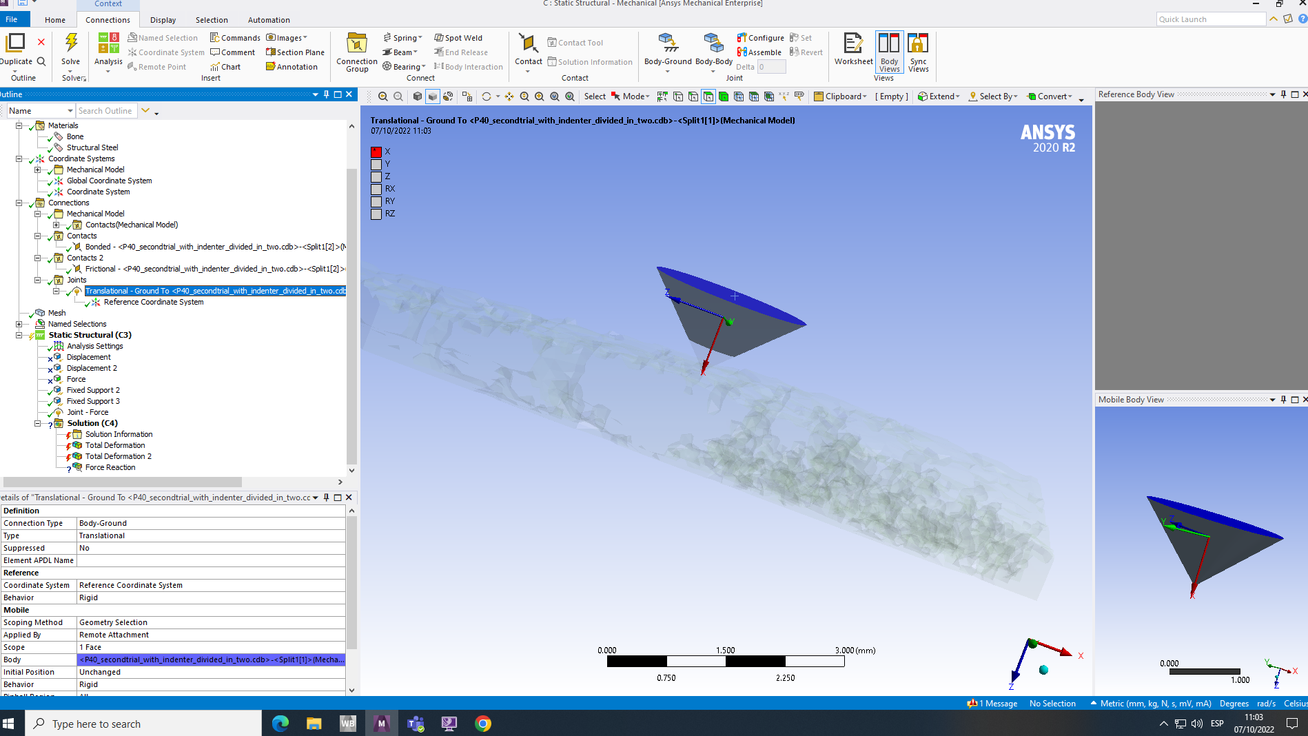
The first problem I see is that the Indenter does not start out touching the bone.
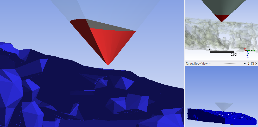
Bonded Contact is on the tip so that the Static Structural model can start. If you don’t have initial contact and have a force driving the indenter, there is no solution if there is no initial contact.
After I delete the Bonded Contact, I ran a Contact Tool to get the Initial Contact Status on the Frictional contact.
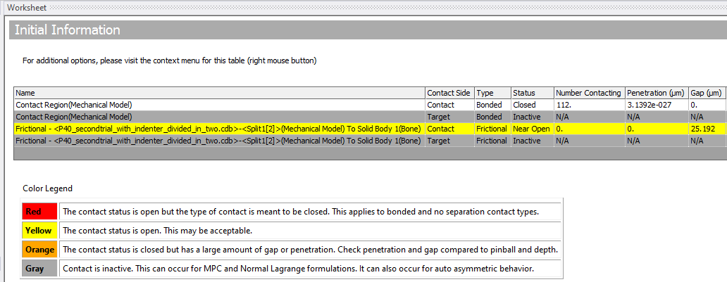
You can see there is a 25 micron gap.
A quick and easy fix for that is to use “Adjust to Touch” in the contact details and it will close that gap automatically by moving the contact surface by that amount. But it might not move it along the Z axis, it finds the smallest distance and moves it in that direction.
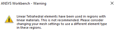
Mechanical issued a warning.
The solver issued a warning.
*** WARNING *** CP = 7.656 TIME= 09:01:01
Meshes made up of 10 percent or more of SOLID185 tetrahedra are not recommended.You should consider following that advice, however the model will take longer to solve.
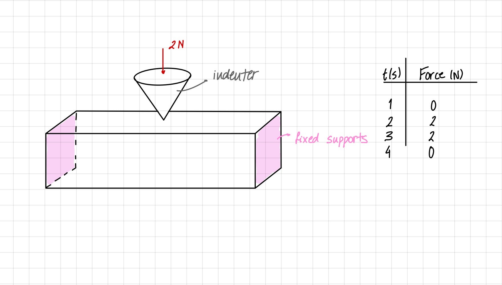
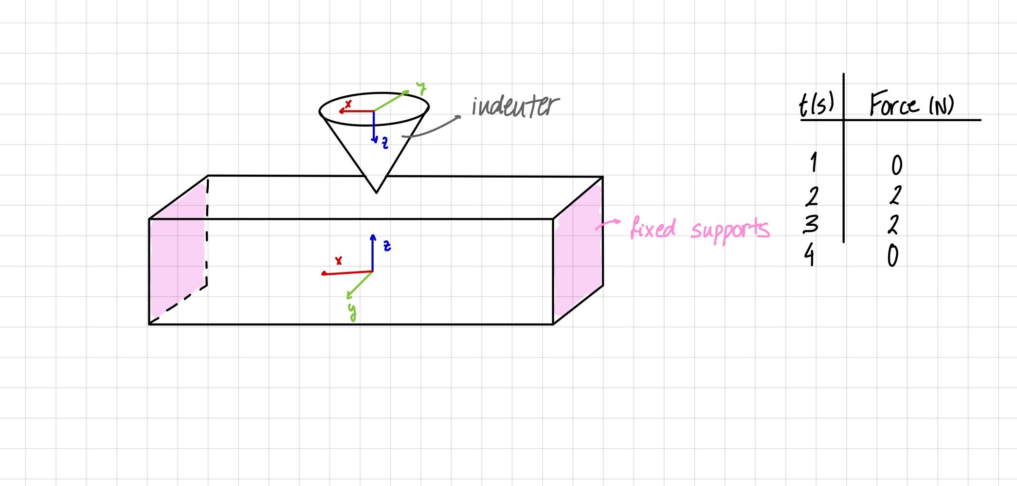
You have 4 steps, but no load is applied in Step 1. I reconfigured the steps like this:
Finally, under Analysis Settings, you must have Large Deflection turned on.
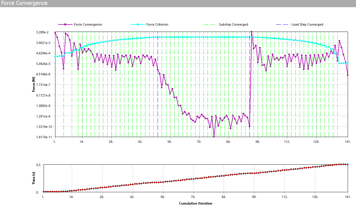
It is solving now with those changes and I will report back later.
Regards,
Peter
-
October 10, 2022 at 3:12 pm
-
October 10, 2022 at 3:23 pm
garazilizaso
SubscriberThank you so much. I have made those changes and I'm running the model. Would you mind if you share with me your model just in case?
-
October 10, 2022 at 8:06 pm
peteroznewman
SubscriberIf you make the same changes I made, you will get the same result. If will send mine if you get stuck, but let's see what happens first. There may be an easy fix if it doesn't work on the first try.
-
October 11, 2022 at 7:38 am
garazilizaso
SubscriberIt worked! Thank you so much Peter
Now the thing is I want to make multiple cycles. So 5 cycles of 2N loadings, and that did not converge. Should something be changed when loading multiple times?
-
October 11, 2022 at 11:54 am
peteroznewman
SubscriberHi Garazi,
I applied 20 N for 200 seconds using the same brief ramp on and ramp off times as before. I got some meaningful deformation at the end. Can you use longer times instead of cycles?
Look in the Solution Output text near the end and see what it says. Depending on what it says, different corrective actions would be used. If you would like to have a live video chat, I can meet to go over the solution output with you on Google Meet or Skype. Reply with your email address and I will contact you. You can delete your email address as soon as I have it.
-
October 11, 2022 at 2:52 pm
garazilizaso
SubscriberThat would be so nice. My email is:
-
October 11, 2022 at 5:27 pm
peteroznewman
SubscriberOkay, you can edit your previous reply. I got it.
-
- The topic ‘Definition of force to simulate an indentation’ is closed to new replies.
-
6495
-
1906
-
1458
-
1308
-
1022
© 2026 Copyright ANSYS, Inc. All rights reserved.


